The Buggy Project
Last Updated: 03/01/2023
My quest to breathe new life into a vintage toy buggy, with 3D printing

Matthew Piercey

Part of a Series:
Matthew's MachinationsA series chronicling my hijinks, across a bunch of random side-projects

Ever wanted to fix something, and you thought you knew where to start, so you just decided take it apart? But you ended up realizing you got in way over your head, so you set the project aside, as a pile of parts, wondering if you’ll ever be able to finish it? Story of my life, honestly.
But not this time, I told myself. No, this time I’m going to follow through. No matter how many hurdles I face, no matter how limited my options, and no matter how far from my original vision the final product was going to stray, I decided that this was one project I was going to see through to completion.
While I’m satisfied with the result, I really wanted to make this post to share the process. And to get a chance to put our brand new blogging engine through its paces. If you’re just here for the finished product, feel free to skip to the bottom. Fair warning, you might be disappointed.
But if you’re here for the journey, the process, the story in all its excruciating detail, then fasten your seat belt. It’ll be a bumpy ride, but we’ll get through this together. I really hope you’ll enjoy it, and maybe learn a thing or two along with me!

If you like seeing the progression of 3D printed models, keep reading!
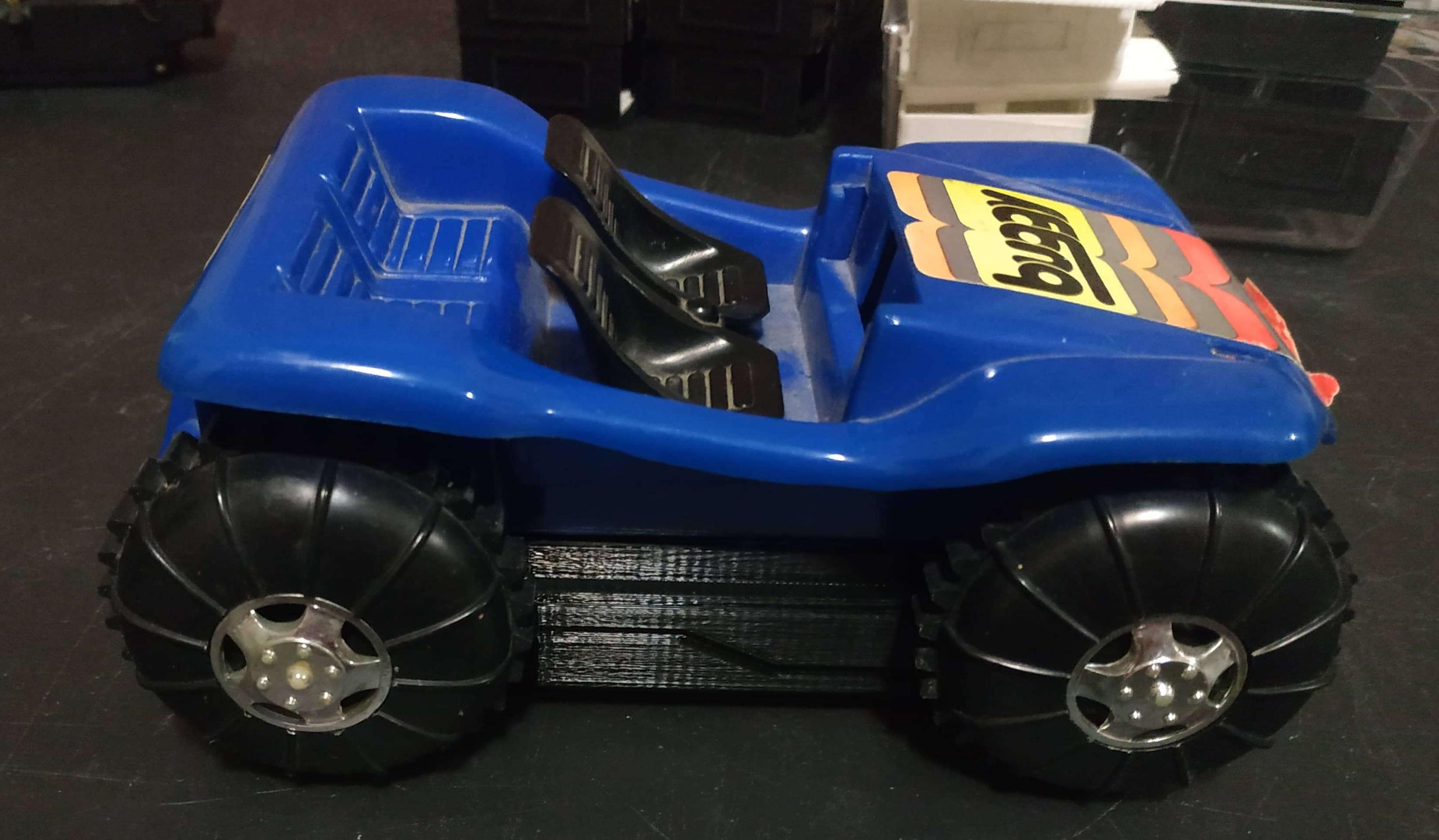
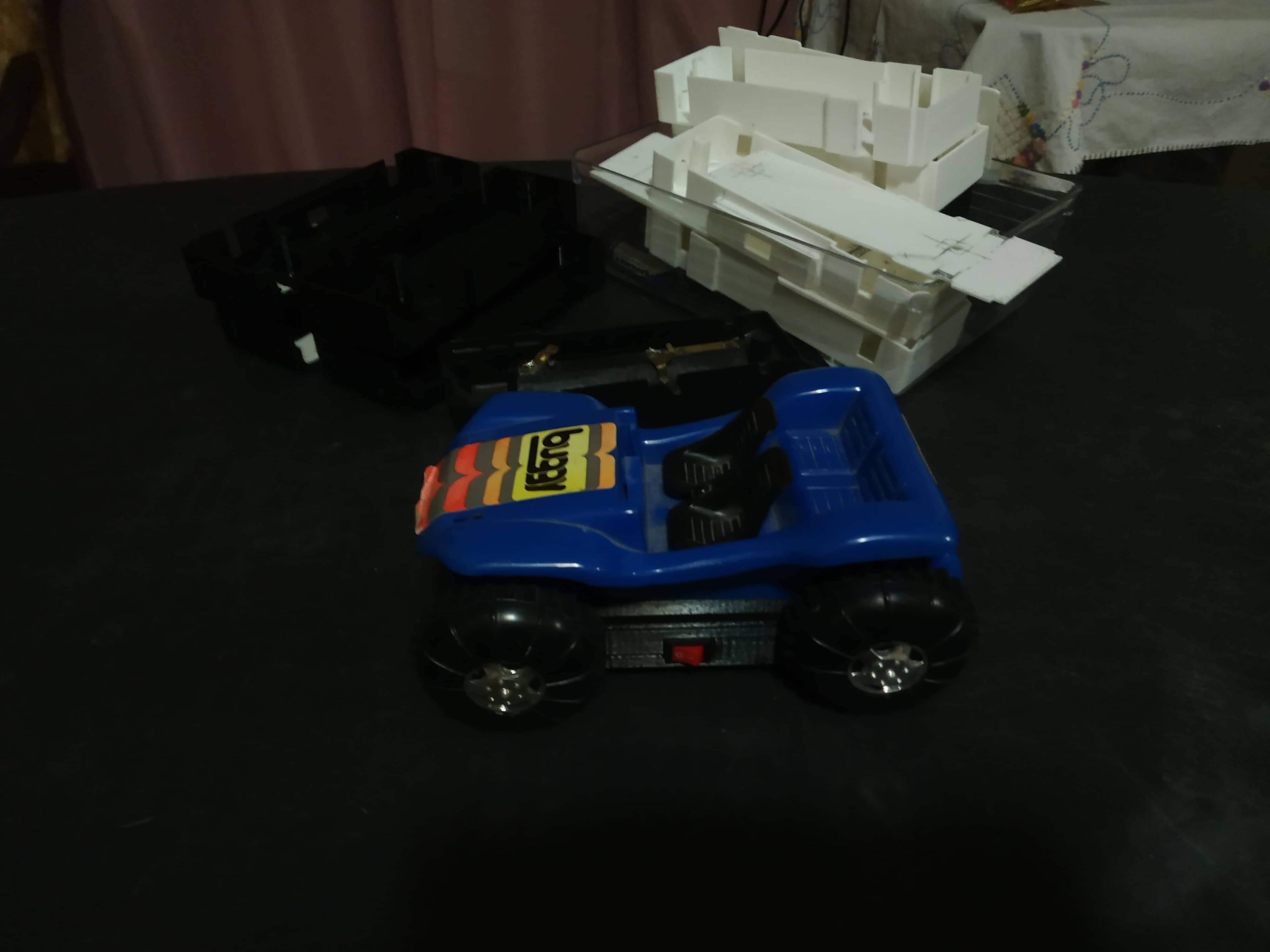
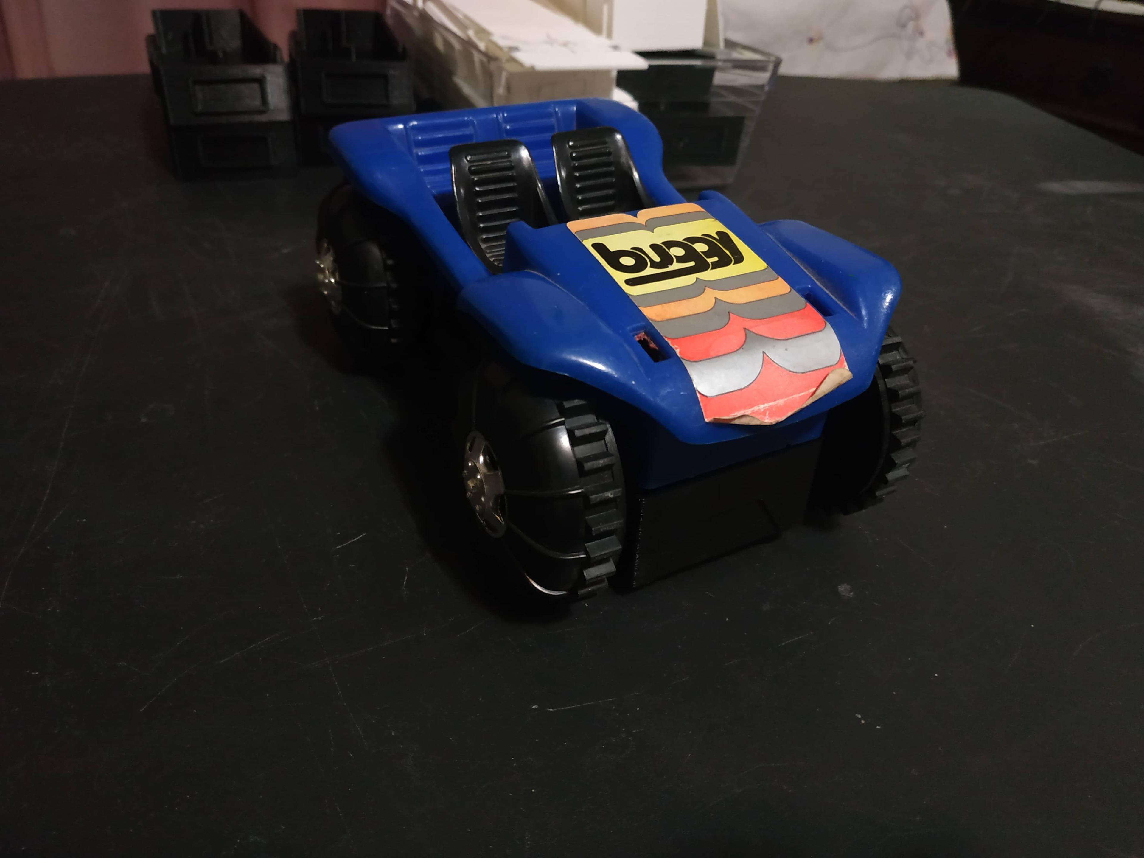
For years, I saw this blue toy buggy sitting idle on a shelf. Presumably from the 1970’s, I always used to wonder if it would ever run again. A number of months ago, I stopped wondering. The answer was yes, if I had anything to say about it!
So, I got to work. With my trusty precision screwdriver set, I took the buggy apart, piece by piece. I realized that there were three main parts.
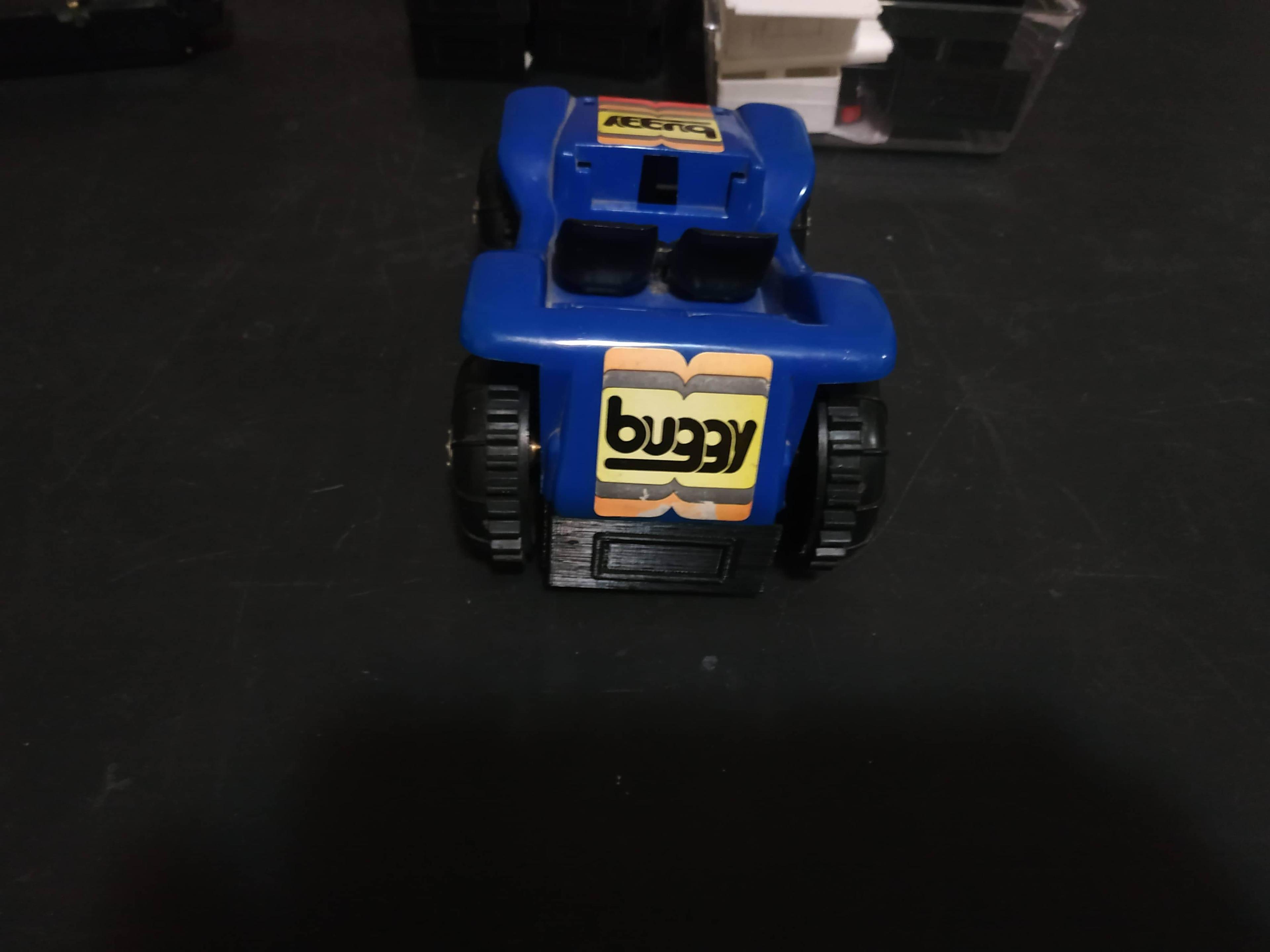
The top piece, made from blue molded plastic with little seats and stickers
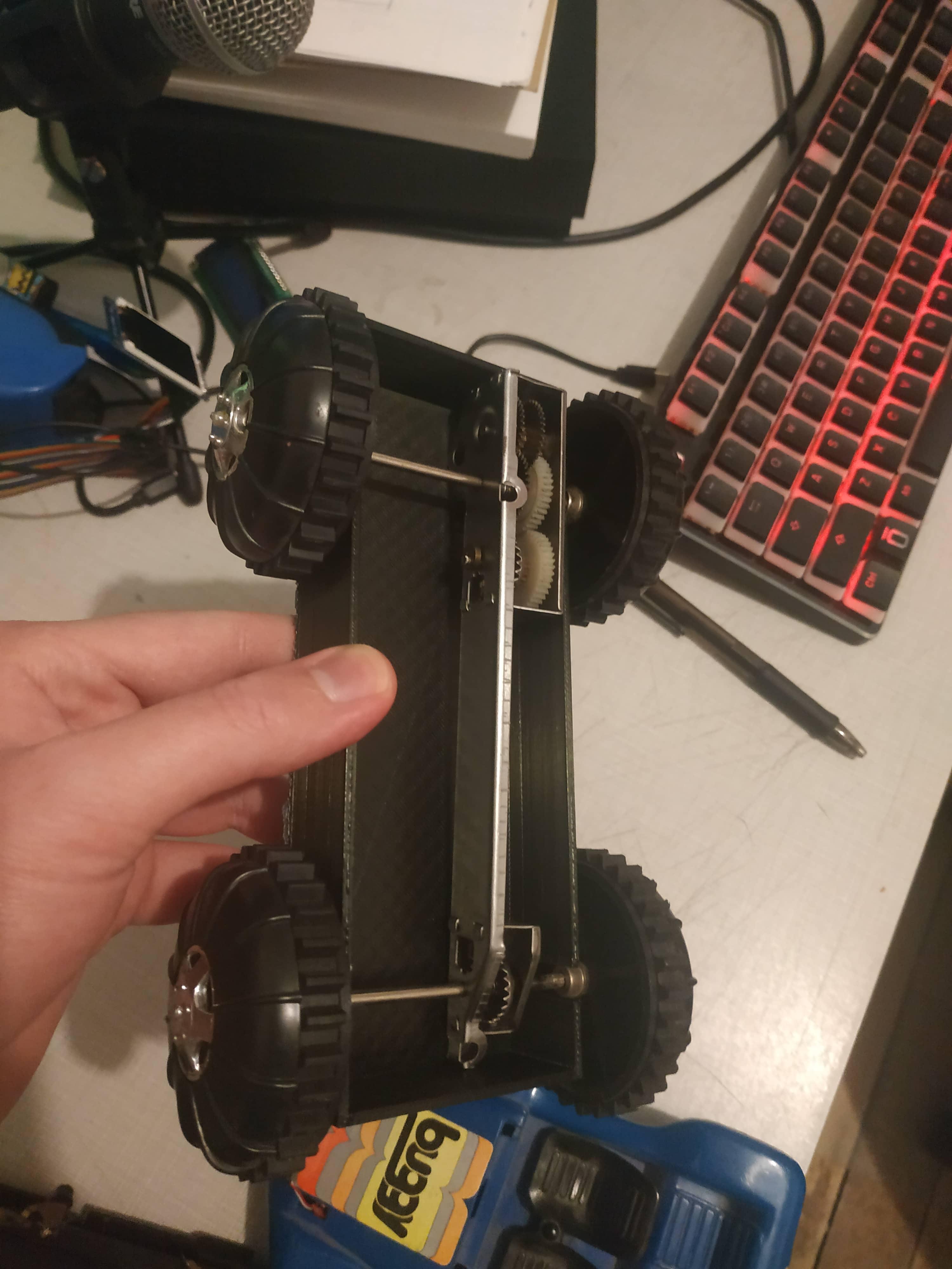
The drivetrain, a simple gearbox connected to four wheels
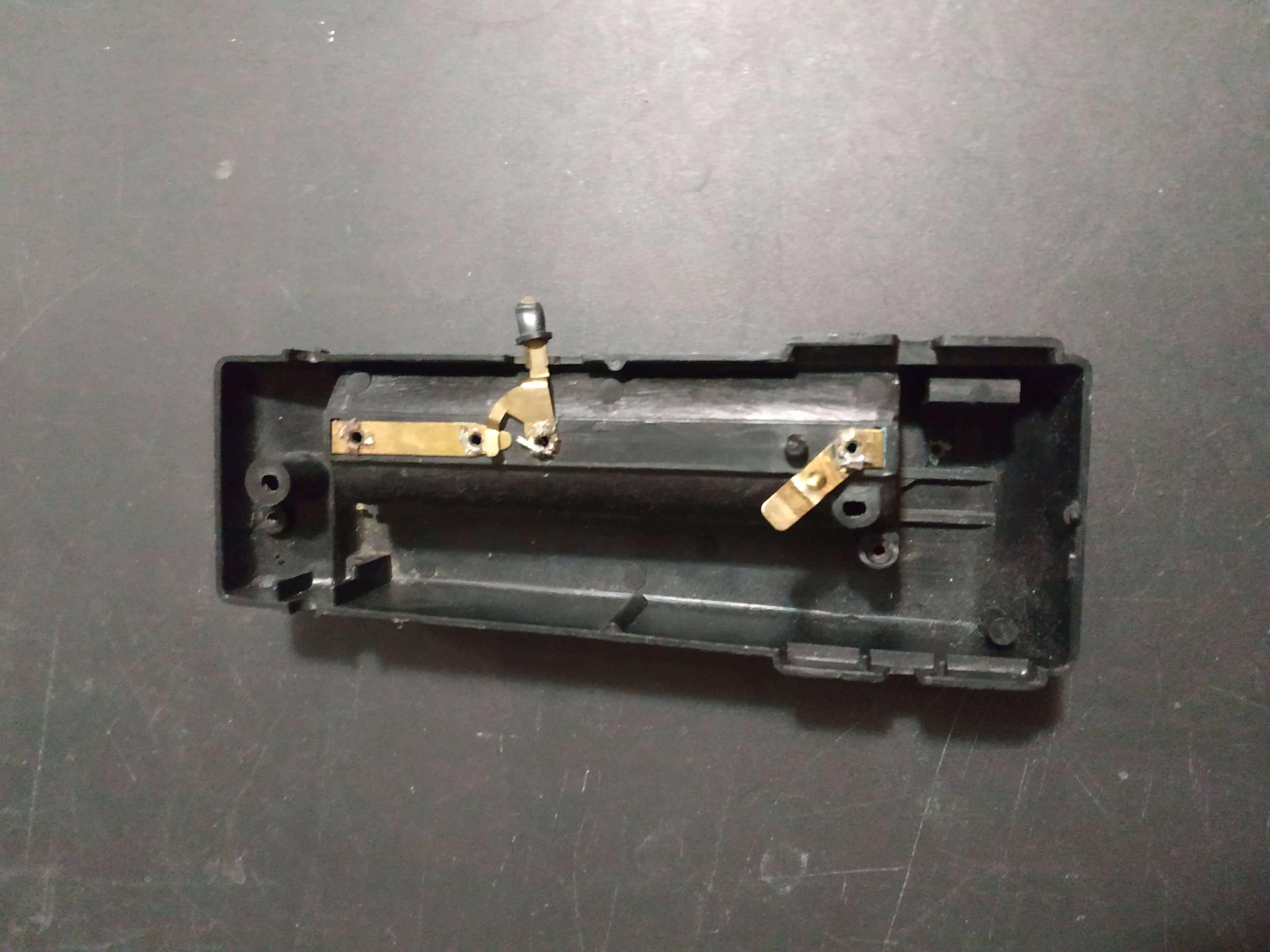
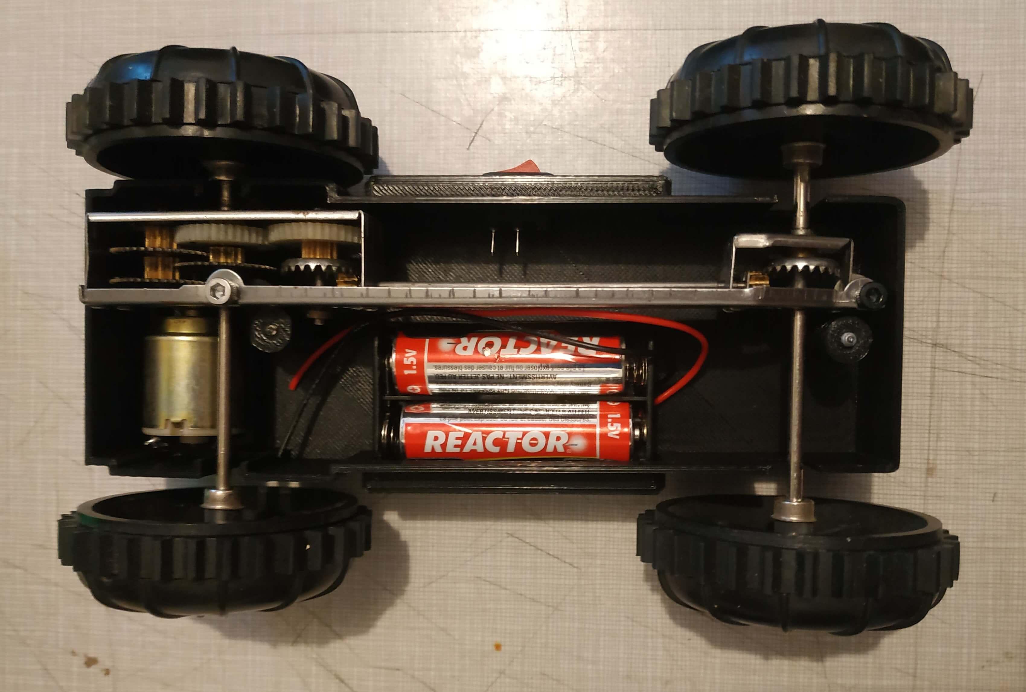
The base, with room for 2 “C” batteries, a motor, and a rudimentary on/off switch
Having educated myself on the basic theory of operation, I set to work figuring out how to make it go “vroom” again. It should also be noted that there were originally two headlights attached to the front of the buggy, but only one was still extant and barely at that.
So, surely it couldn’t be too difficult, right? Batteries + motor = vroom, right? Well obviously, but then why wasn’t it working when I put batteries into it? Enter metal’s worst enemy - corrosion.
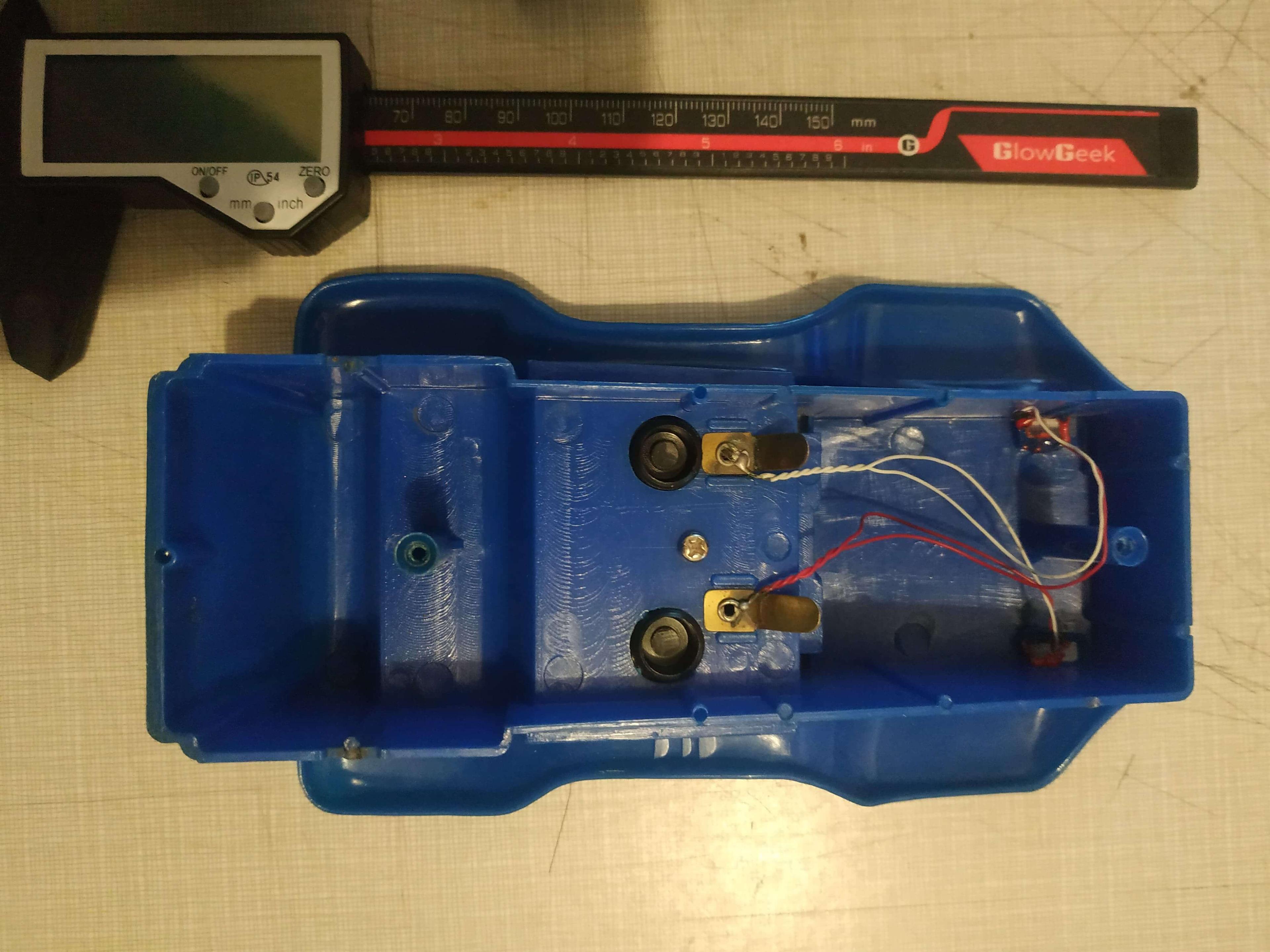
Yep, the contacts on the base, especially around the battery compartment, were incredibly corroded. I don’t know why I even bothered trying to put batteries in it in the first place. There was some blue crystalline sludge on the battery contacts and the motor’s contact, as well as a heavy layer of rust on most of the exposed metal, including a screw and the hinge for the battery compartment.
I tried removing the corrosion with a cotton swab dunked in a ~50/50 mixture of baking soda and water. This is my go-to for corroded battery compartments; I’ve saved several remote controls and forsaken toys this way. It definitely helped, and I removed most of the surface gunk. Then I took my Dremel to some of the heavier nasties. I carefully buffed them out with a wire brush attachment, so most of the surfaces looked shiny once more. Surely, this would be enough, I thought.
Check it out! Unfortunately I don't have a before photo, but everything that's shiny here used to be rusty and heavily corroded
So, that was enough, right? Right?
As is soon to become a running theme in this story, unfortunately, no. It’s a bit of a blur now, but in retrospect I think it wasn’t enough, because I only removed some of the surface corrosion that was easier to get at with a cotton swab and my Dremel. Because at this point, the wiring for the motor was still in place. I didn’t want to disturb it if I didn’t have to.
In retrospect, if I was going for a “proper” restoration, I maybe could have temporarily removed the motor, then bathed the whole base in vinegar or something. It’s possible that could have taken off enough of the corrosion to allow the motor to be properly powered. But I didn’t do that. Instead, I hatched a far more ambitious, but far more interesting plan.

If you squint, you can still see some corrosion in the corner that I couldn't get at without taking the whole thing apart
So, what was this plan of mine? Well, let’s just say it involves a little thing I like to call Additive Manufacturing (AKA 3D printing). That’s right, I decided that I was going to take it upon myself to design a 3D-printed base for the buggy, to allow it to vroom once more, in style.
I quickly got to work…
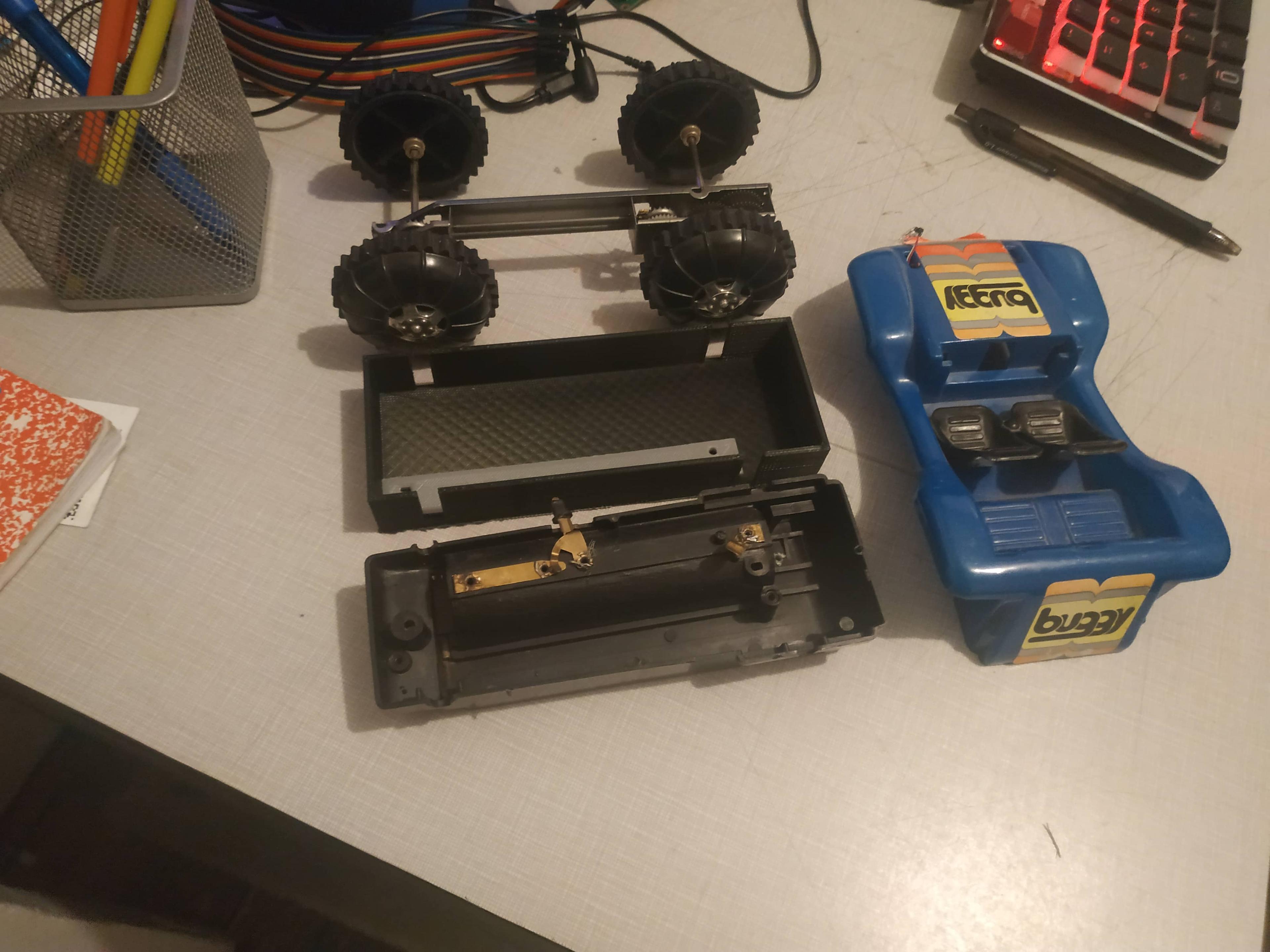
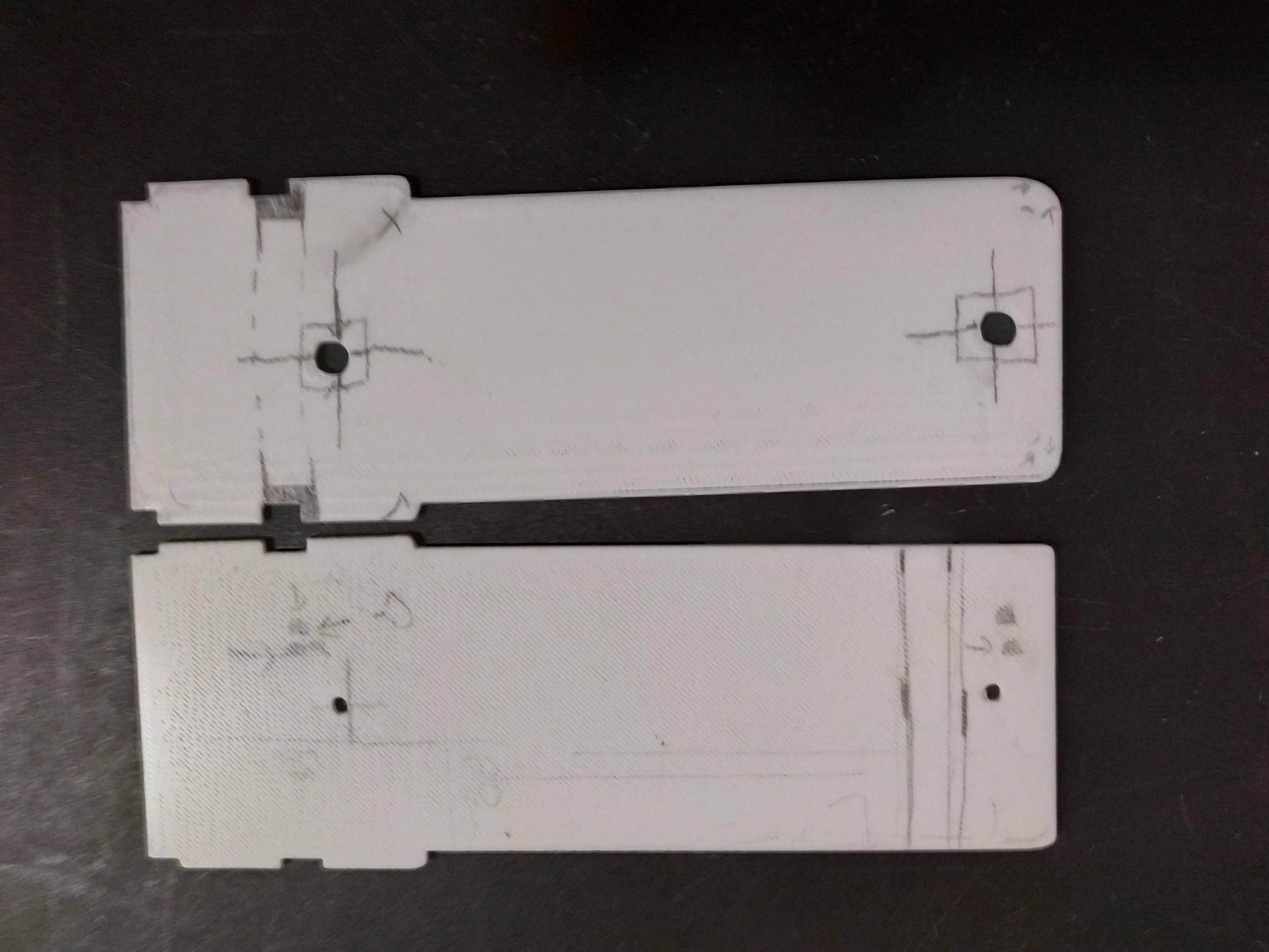
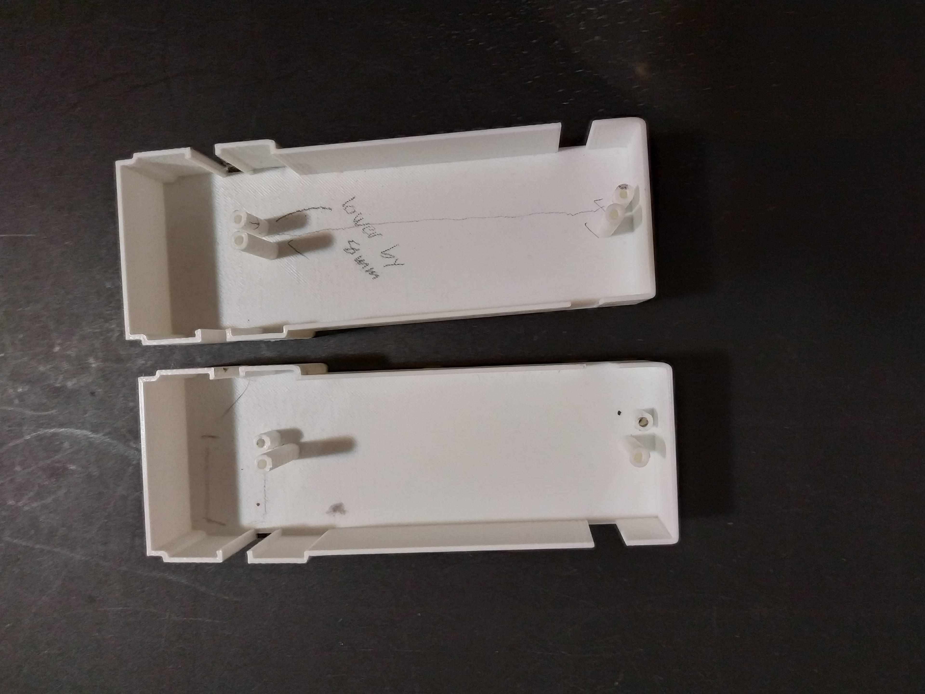
My first two designs (the box with cut-outs for the axles and the grey rod with approximate screw holes) are in the middle
Even at this very early stage, I could tell this had the potential to work
Here's a shot of the underside of the top of the buggy. Note the two posts for screws, and the wires for the lights. One of the lights is straight up missing, and the other was barely holding on, which I ended up taking out.
So, I made some progress, then I got discouraged and basically gave up for four months...
Hey, like I said above, this was a bumpy ride, and I’m going to tell this story as it went down. But basically, I got discouraged at my initial prototypes, because they didn’t hold up very well. This was back when I was using a Wanhao Duplicator i3. Not a bad machine by any means, and definitely more capable than most would give it credit for. But as far as 3D printers go, this one was fairly old, not super reliable, and pretty needy in terms of maintainence and little fixes. But I cut my metaphorical teeth on it, and I wouldn’t trade those experiences.
That said, if I ever wanted to complete this project, I needed a printer that I wouldn’t have to babysit. One that I could start up, then go do something else without having to worry that it was going to make a hot plastic mess. Enter the Prusa i3 MK3S+!
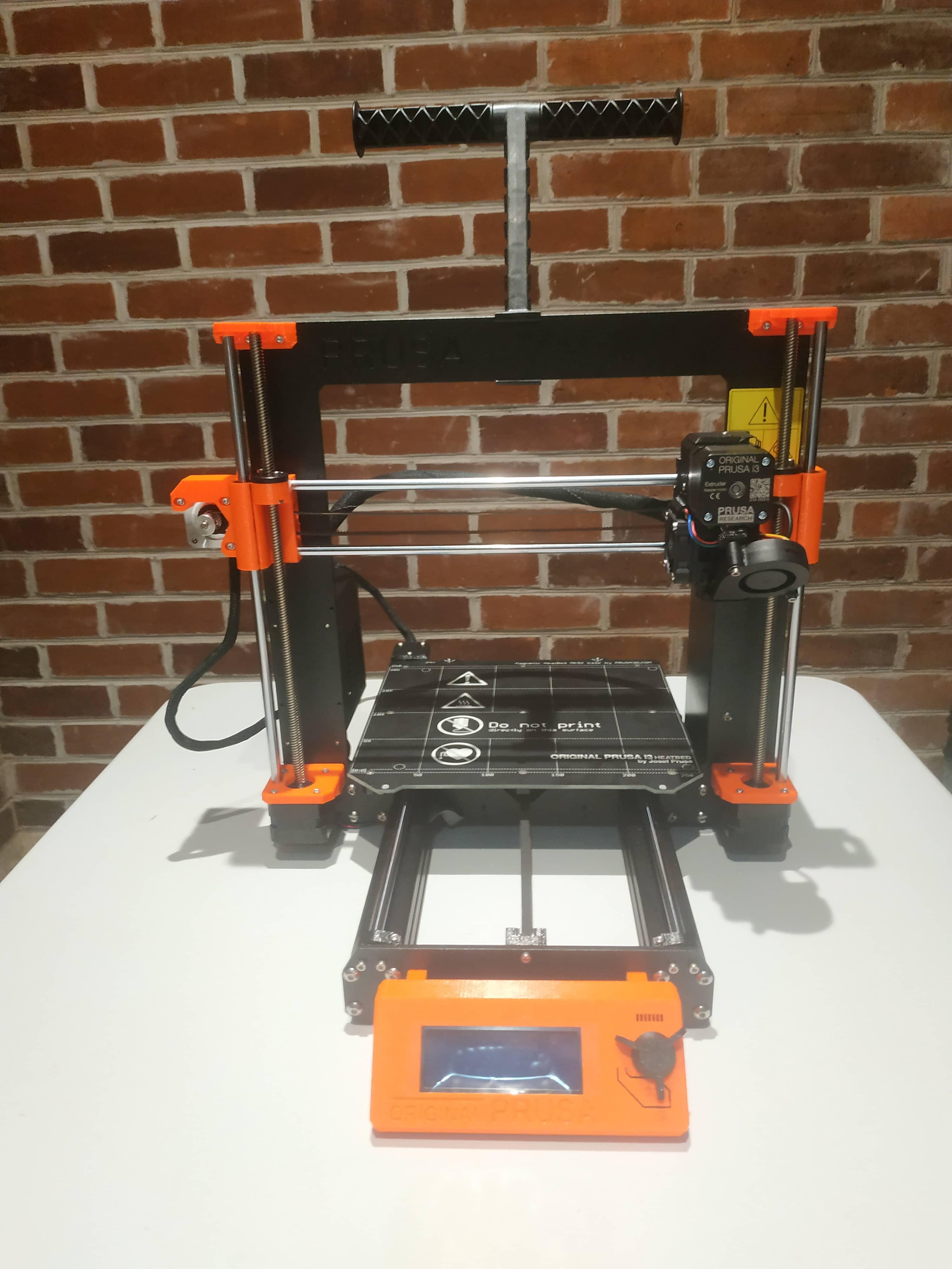
Assembled this thing from a kit, but that's a story for another time
OK, so I didn’t buy a Prusa i3 MK3S+ just for this project. Or did I?
But either way, it definitely came in clutch, and I don’t think I would’ve had the patience to endure this project without it. Like, sure, Prusa’s are not exactly cheap. But it’s the precision and reliability that won me over. I can’t overstate just how much of a gamechanger having a printer that doesn’t mess up and make a bunch of plastic spaghetti every couple of attempts is. I was able to design a new iteration, send it to the printer, get on with my day, and have the finished part waiting for me in the evening. Like I said, the unrivaled reliability of my new 3D printer was a major reason why I was able to finish this project in the first place. Anyway, let the printing begin!
But, wait a second, what was the plan again?
OK, OK, let’s back up. I clearly needed to make a better plan, because “I dunno, just wing it” wasn’t going to work.
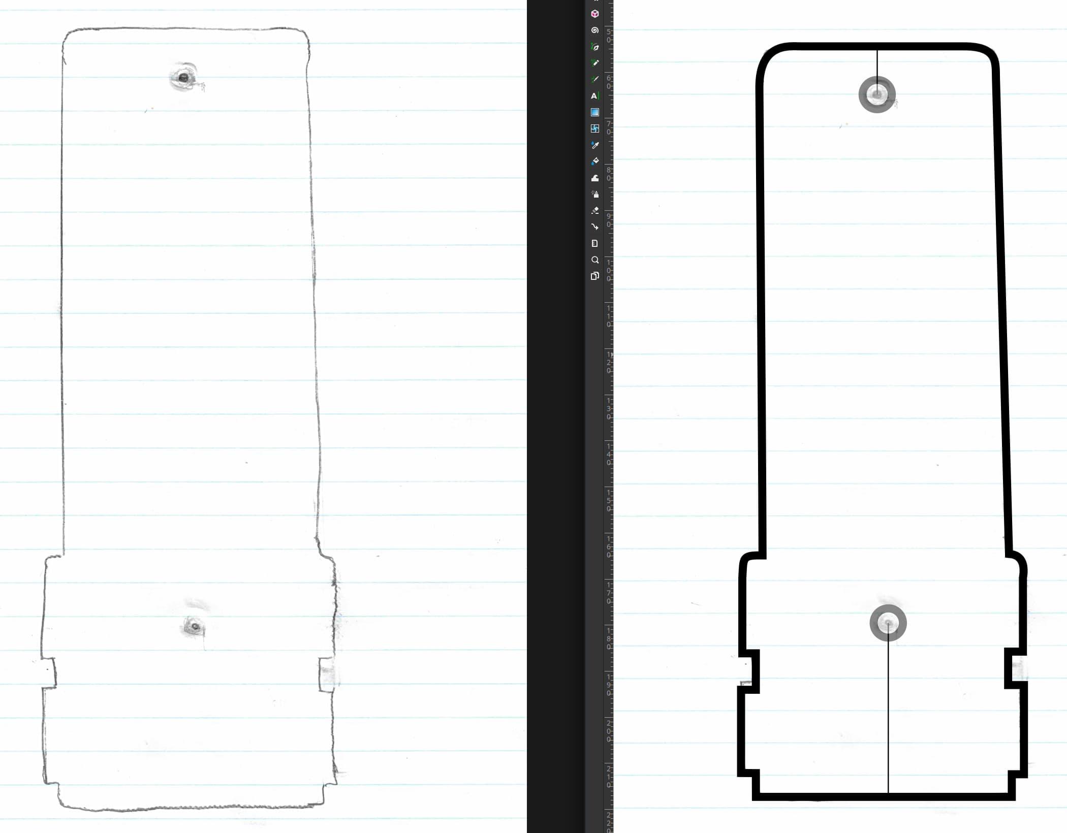
Below is a picture of the first buggy part I tried to print with my new Prusa 3D printer, after giving up for about four months. I based it off a photograph of the base of the buggy, which I imported into Inkscape (a free, open-source vector graphics editing program similar to Adobe Illustrator).
Seems legit, right? I sure thought so.
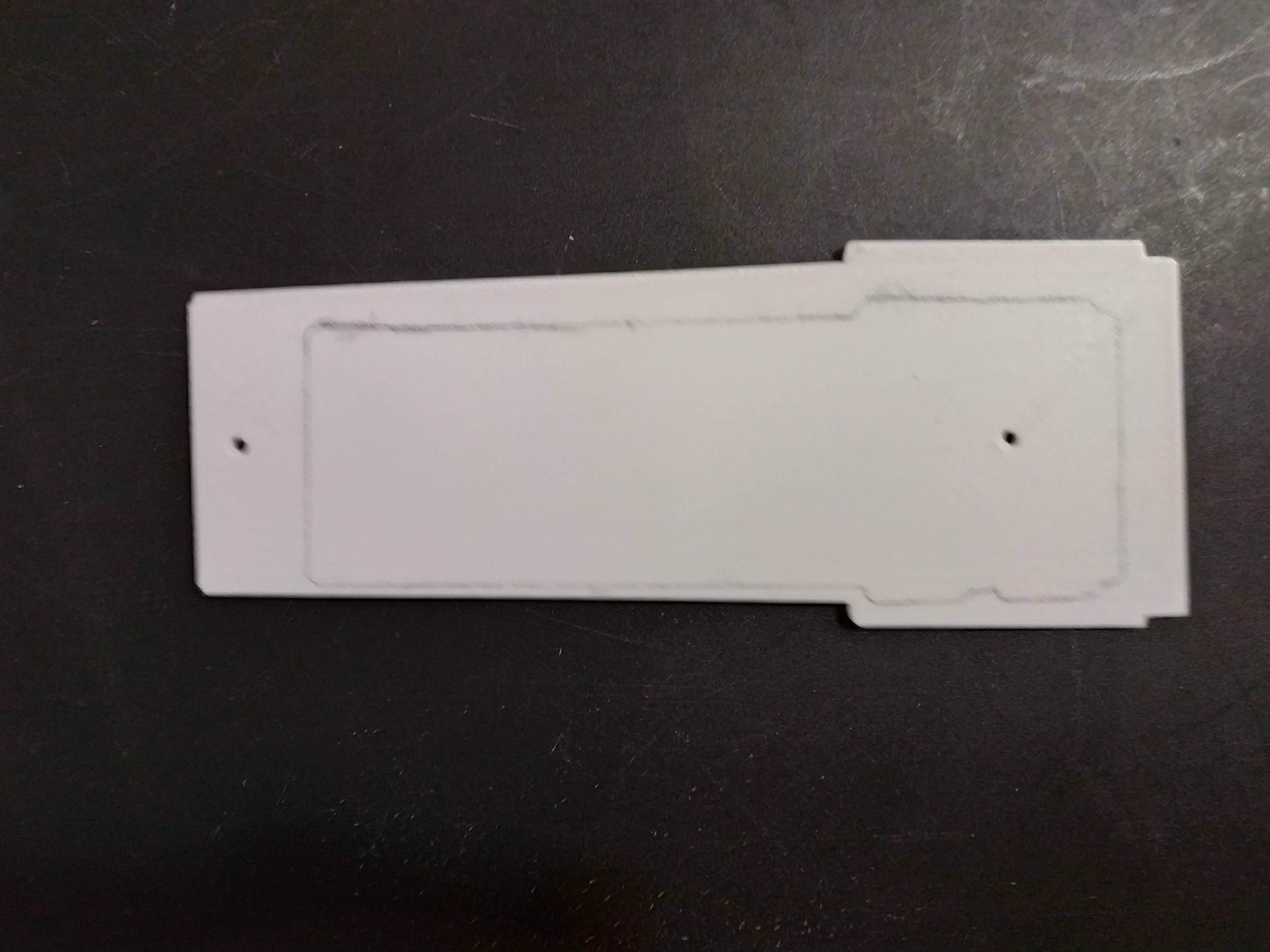
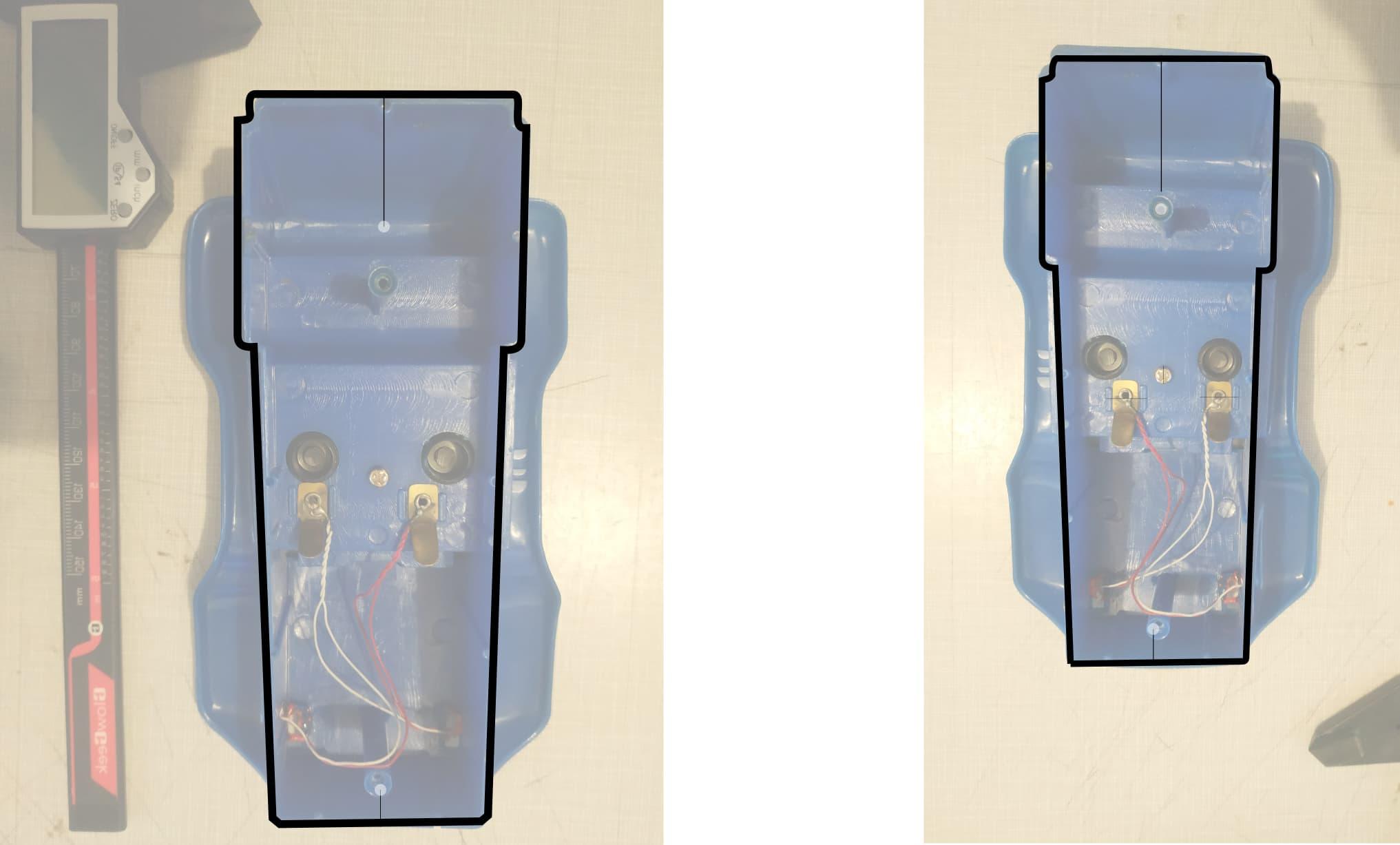
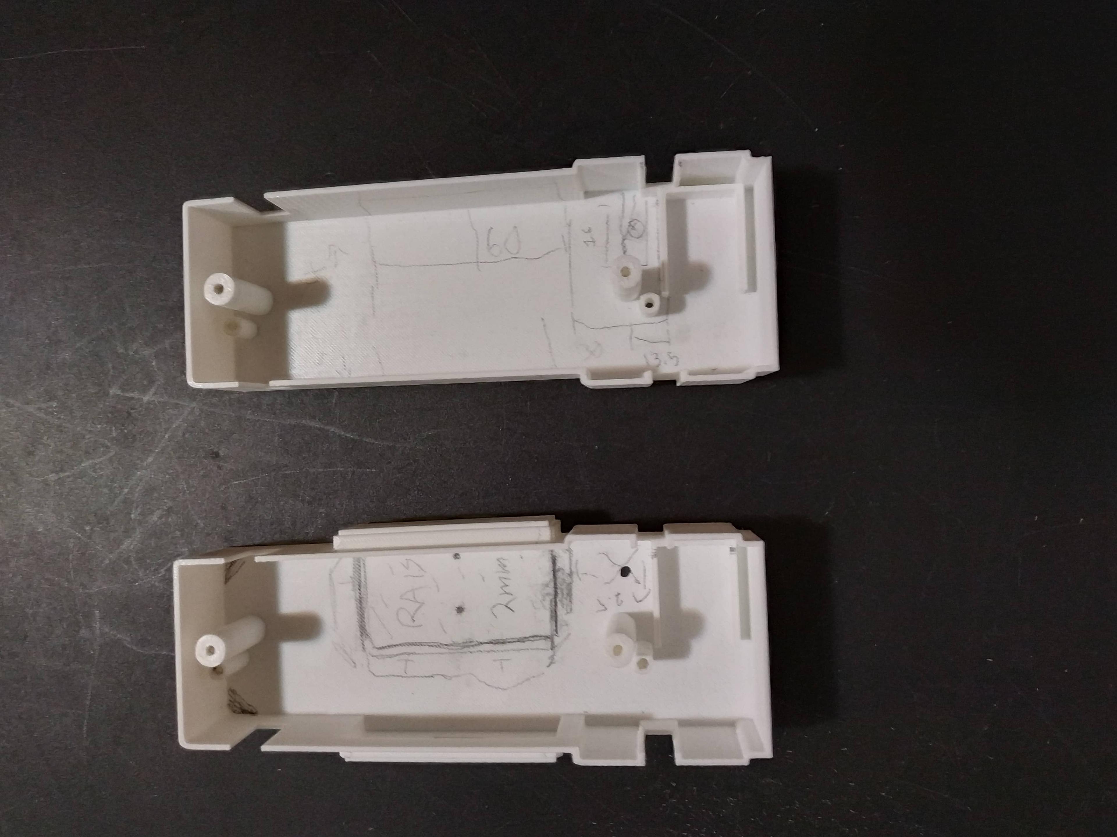
This doesn't look right at all (the pencil is the actual outline of the buggy). But, it taught me a neat trick. If you print with light-coloured filament, you can mark up the part with a pencil!
As those pictures demonstrate, sometimes a method really looks like it’s going to work. But it takes trial and error to realize that it does not, in fact, work.
But my heart was in the right place, I figured. I decided that the plan was to design the 3D printed part approximating:
The outline of the buggy itself (where the top part connects to the base)
The placement of the four screws (two for the top part, and two for the base)
The placement of the motor
While there were other considerations (like how to mount the motor, where to put the batteries, or what kind of on/off switch I was going to use), I had to start somewhere.
And here’s the first major lesson I learned from this project. The best way to set yourself up for success with a design project is not to try to design the whole thing in one go. You need to adopt a somewhat scientific approach - eliminate one variable at a time, and build on your successes. Alongside that lesson, find a way to fail fast. Iterative progress can be incredibly frustrating if it takes a long time between prototypes. Thanks to the magic of 3D printing, though, I could make a new 3D design, and be able to hold it in my hands in a matter of hours.
OK, this sounded like a much better plan. Chip away at the first few variables, then just keep going until I’m satisfied with the result.
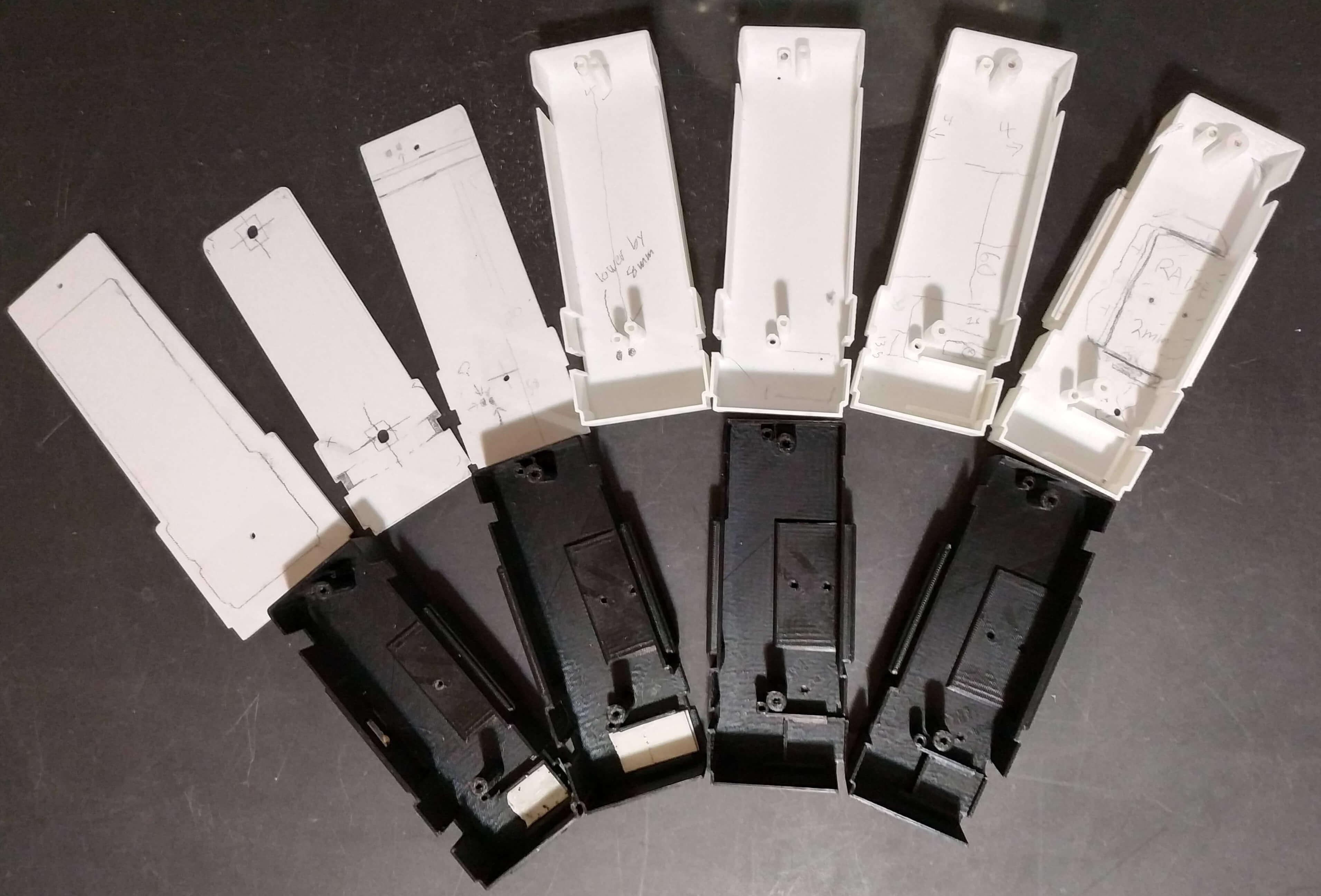
To that end, I decided to sketch out the outline of the top of the buggy, using it as a stencil on a sheet of notebook paper. I then took said paper, scanned it, and imported the scan into Inkscape. I think the main problem with using a photograph was that, even though I tried to capture it straight on, the camera added a perspective which warped the dimensions.
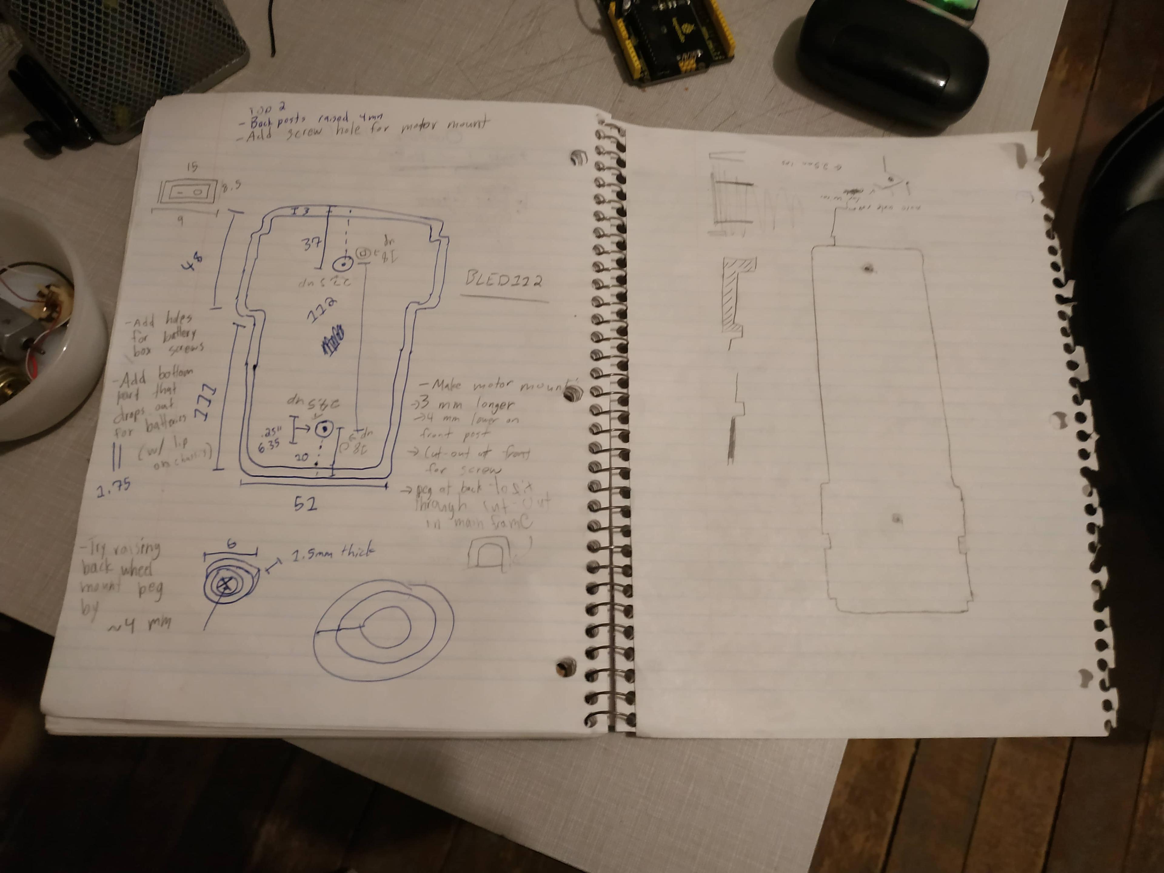
I may not keep the neatest of notes, but these scribbles have served me well!
Now we're getting somewhere! Note how I was able to mark up proposed changes for the next iteration. Super helpful, let me tell you.
Fun fact, up to this point I wasn’t actually designing a 3D model. As one of the above pictures shows, I was actually designing a 2D vector outline in Inkscape.
So it if was just a 2D outline, how was I able to 3D print it? Enter FreeCAD.
FreeCAD is a free CAD program (oh really? never would’ve guessed). It’s not the best or easiest to use, but it’s kinda grown on me. In my opinion, one of the things I like the most about FreeCAD is how easy it is to import/export different types of files.
For instance, I was able to import the “SVG” (Scalable Vector Graphics) 2D outline I made in Inkscape directly into FreeCAD. I was then able to extrude it into a 3D model. Another thing I really like about FreeCAD is how you can do boolean operations with different parts of a model. For the uninitiated, boolean operations allow you to combine shapes in a number of different ways. You could, for instance, add two shapes together (FreeCAD calls this a “union”). You could subtract one shape from another (a “cut”), or keep only the “intersection” of two shapes.
Here’s a fun visual to help explain boolean logic, by Kaz Miyamo (@38mo1 on Twitter).
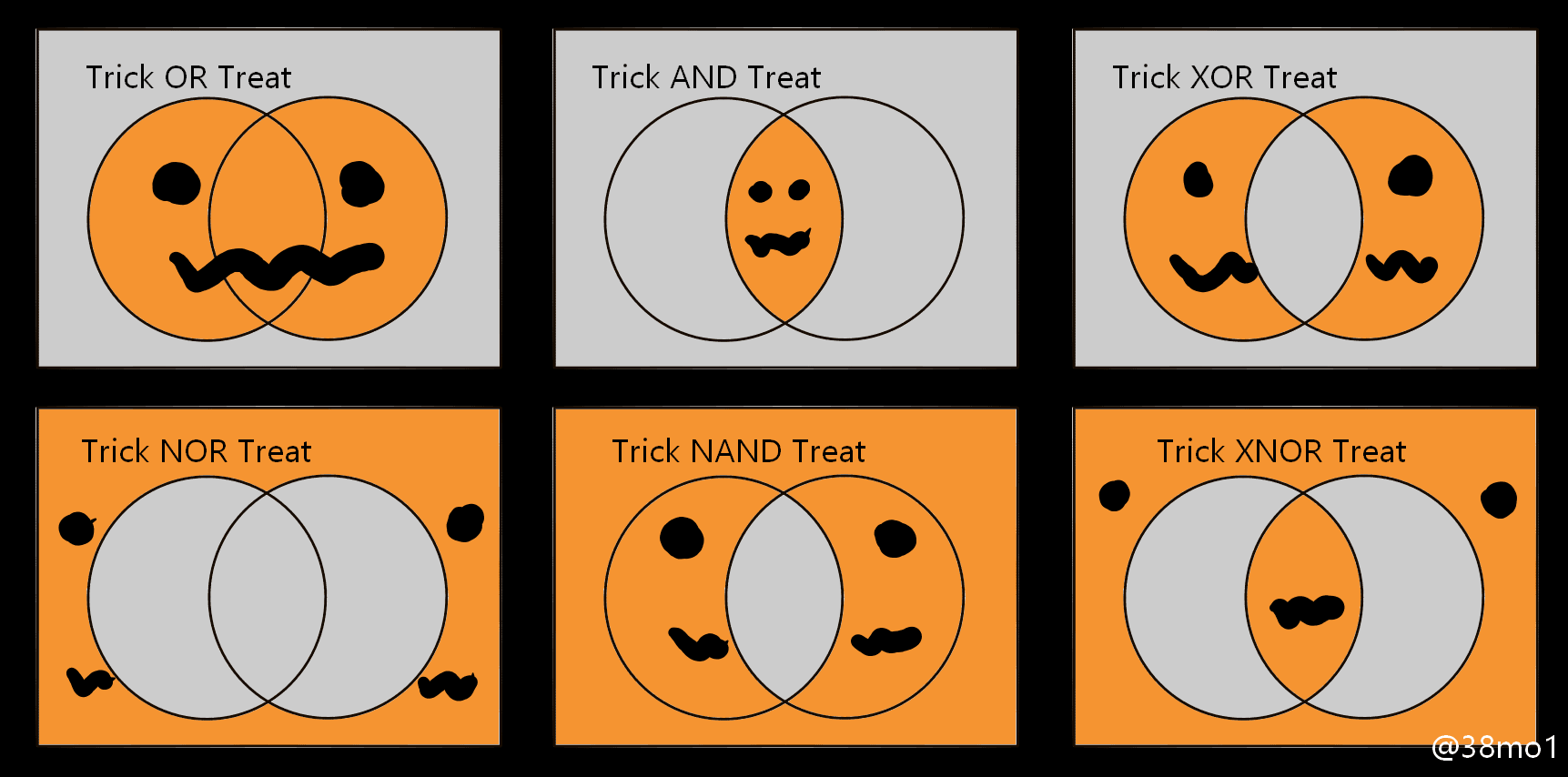
Trick XNOR Treat!
Bringing it back to the buggy, I was able to use the boolean logic and 2D-to-3D extrusion tools in FreeCAD to convert my flat outline with screw holes into something a bit less flat:
Kinda wild to think this design started its life in a 2D drawing program
I was able to iterate much more quickly this time around. After coming up with a basic outline that fit the top part of the buggy, I was able to create posts for connecting the drivetrain and top part to the base, with the help of some M3 screws.
Hmm... well the drivetrain fits. That's a good sign.
Yay, success! I'm almost done, right? Right?
It took a couple attempts, but I was able to get a good fit soon enough! The drivetrain and top part were together again, and my design had brought them together. This was definitely a milestone in this project. But as I was about to see, I still had a long way to go…

Bit of foreshadowing trying to find a place for the motor here...
At this point, I had completed what I thought at the time was a pretty difficult task. Through trial and error, following a scan of a pencil sketch, and with the help of my trusty calipers, the initial phase of the design was ready to go.
It was definitely interesting to make the design in Inkscape and flesh it out with FreeCAD. But I knew that if I wanted to take this any further, I needed to do some actual 3D modelling.
That was something I was somewhat hesitant to do, since I wasn’t very comfortable with FreeCAD at the time. I don’t know, I just got spoiled with the “simplicity” of Google SketchUp, a tool which I used for several years. (I would very much not recommend using SketchUp for anything you want to 3D print, especially in this day and age.)
SketchUp is really an architectural software, though. Using it for mechanical design is a bad idea, in my opinion. Many had recommended Fusion 360, and I’m sure it’s a fine tool, but I didn’t feel like using something that wasn’t necessarily free. I tried my hand at some other options, like OpenSCAD and CADQuery (which are both really cool programs that are worth a try if you’re really into “programmatic CAD”). And of course there’s Blender, although it’s more of an art program.
So, FreeCAD it was. I decided stubbornly that I was going to figure out how to use it effectively. I wanted to get into the same sort of “groove” that made me a SketchUp hold-out for so long. And I’m pleased to say, even if this project was nothing else, it gave me an excuse to finally find my groove with FreeCAD. And now, with a powerful CAD program and a ultra-reliable 3D printer at my disposal, it was time to get to the bottom of this!
So, what was left to do? Well…
I had to find a way to secure the motor
I had to decide on what kind of batteries I was going to use, and where I was going to put them
I needed to find an on/off switch.
And truthfully, this is the part of the project where I had to limit the scope, or I would never have finished it. I had originally thought to use something like a Raspberry Pi Pico or ESP32 computer board, in conjunction with some kind of rechargeable Lithium battery (with a USB charging port), and some LEDs to replace the old, missing headlights. But I had to come to terms with the fact that I didn’t have the space or the expertise to pull something like this off. Maybe someday I’ll revisit this project and add those features. But for the time being, I had a project to finish, not delay further.
In my opinion, this is a valuable lesson for anybody working on a passion project, of any kind. It’s almost always better to limit the scope of the project, and actually finish it, then to try to make it exactly like you originally dreamed it would be. Because dreams can sometimes come true exactly as we thought they would. But I think it’s better to be open to new possibilities along the way. Sure, sometimes that means you might be disappointed with the result of a given project (arguably not more disappointed than you would’ve been if you never finished it), but it might end up turning out better than you could have ever expected. And either way, any project can be a learning opportunity, if you let it.
But enough motivational speaking, I’ve got a buggy to finish!
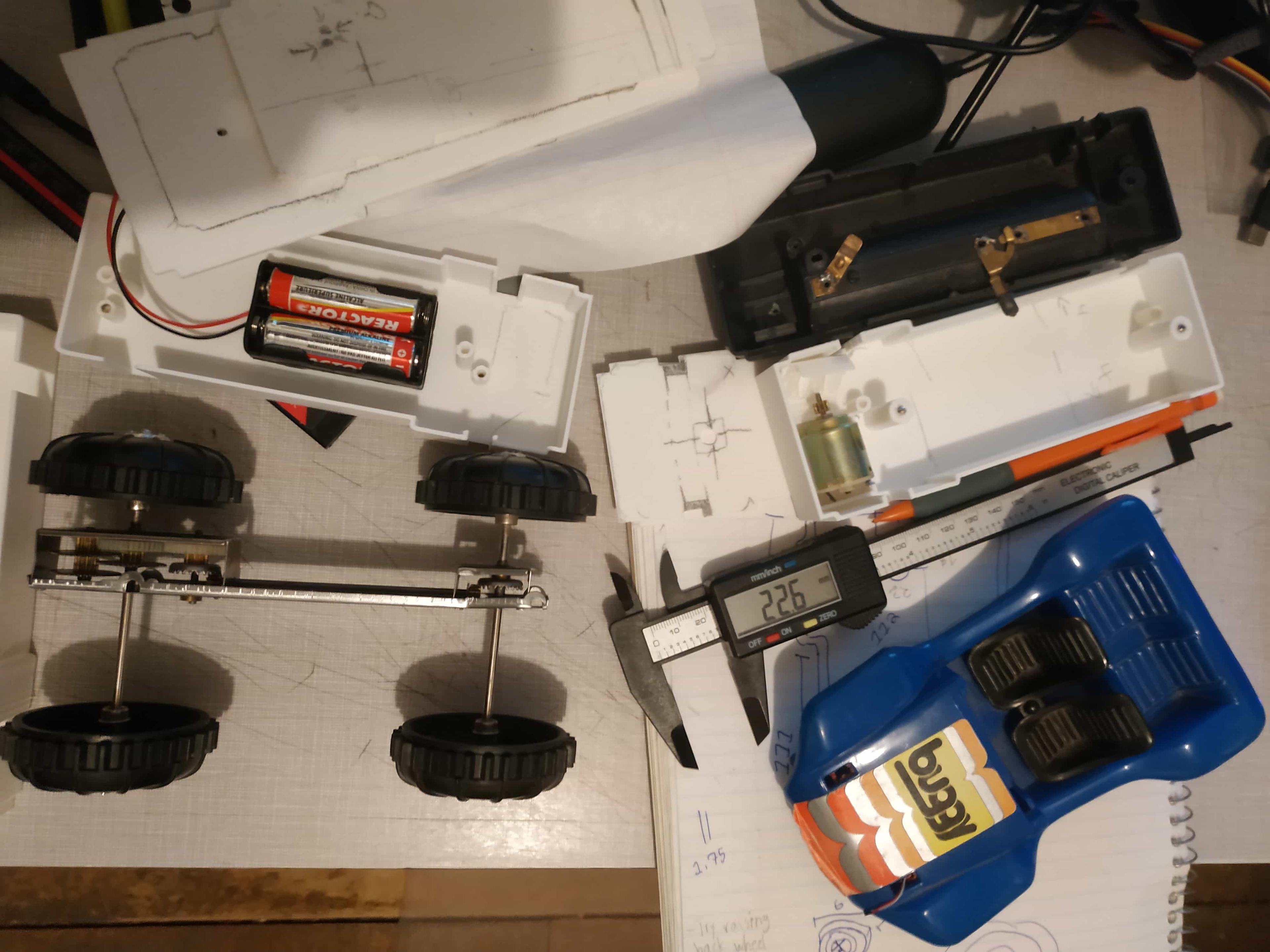
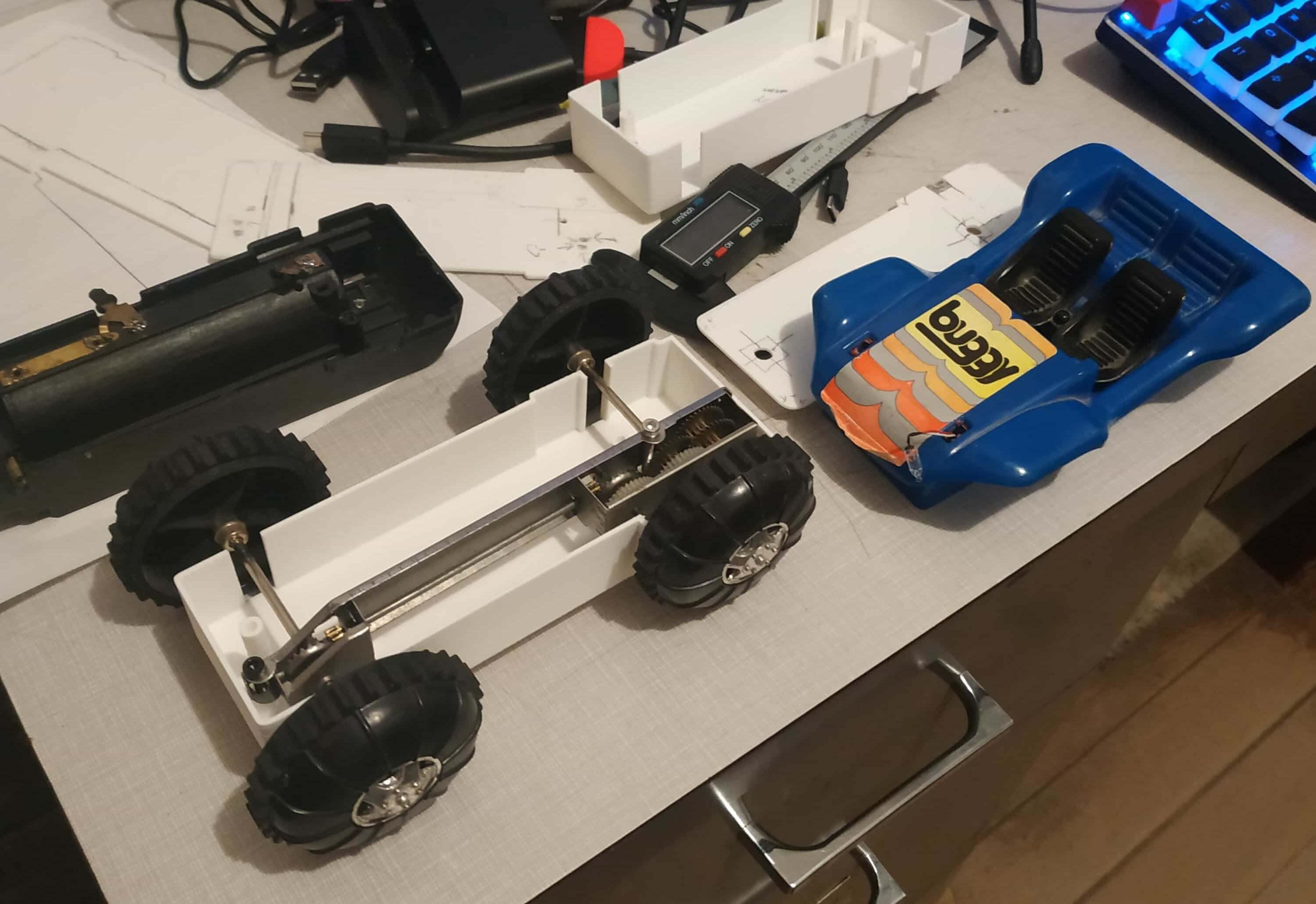
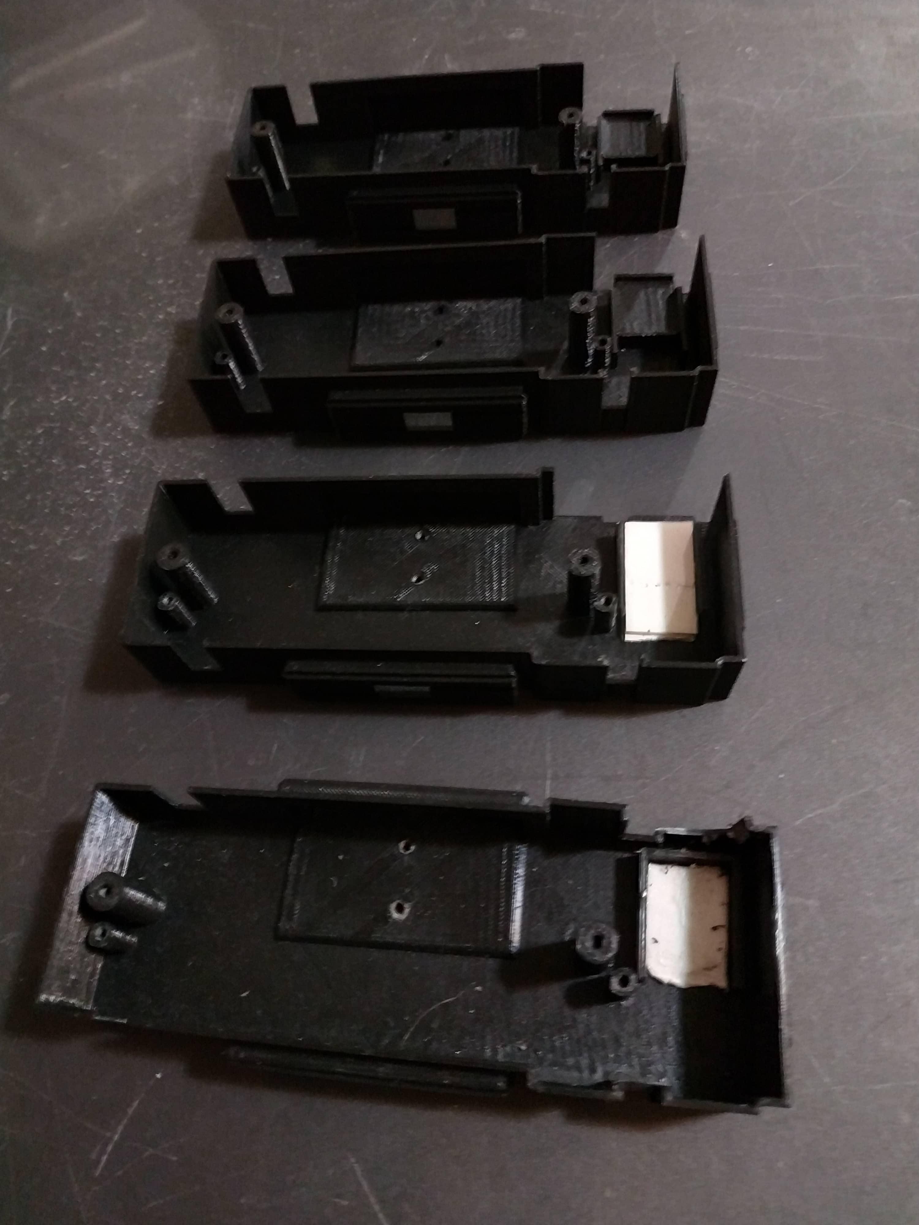
Here you can see I'm testing out where to fit the batteries (I'm going with two AA's) and the motor
The bottom design was when I first started doing some actual 3D design. You can see the place for the motor and batteries is shaping up...
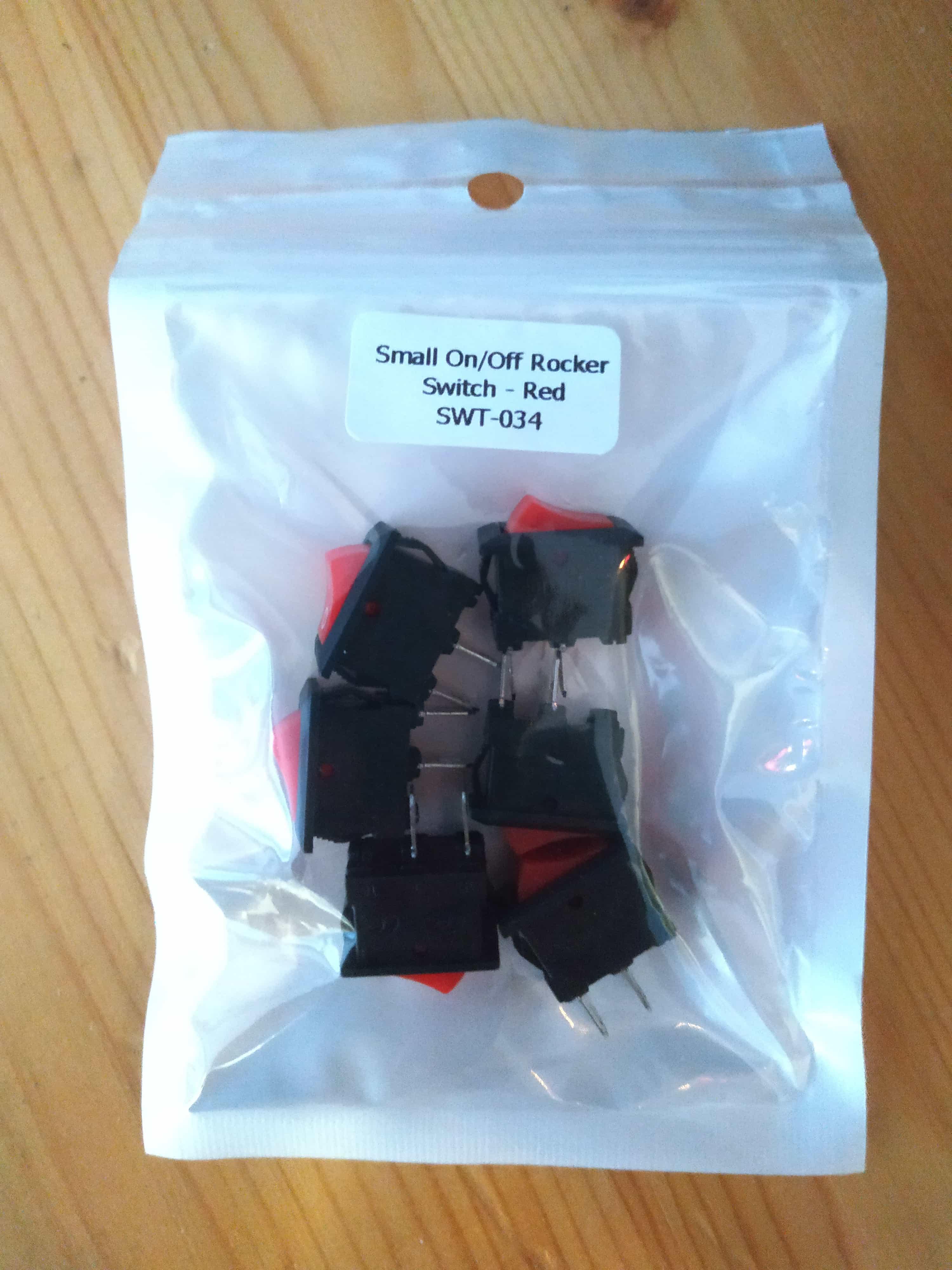
Picked up some perfect little switches from BC Robotics
At this point, I now had a place for the motor (sorta), the batteries, and a wonderful little rocker switch. I ordered my switches from BC Robotics, and they were honestly perfect.
Note that I said “switches”, not “switch”. But why did I order several, you ask? Surely the buggy only needs one? Well…
Noooooo! What have I done?!
Yeah, so I may have melted the first switch I bought, rendering it inoperable. So I made sure to order more than one next time. Fool me once…
In order to understand how I managed to melt the switch, you must understand that I’m not very good at soldering. Honestly, the wiring was hands down the most stressful part of this project. Designing and printing the 3D models? Easy. Buying the electronics I needed? Not too bad. But, ugh, I did not enjoy the soldering. Mind you, I think I’m slowly getting better at it. I finally know how to use flux properly, and I can’t complain that my soldering iron isn’t good enough (I was using a Hakko FX-888D, widely regarded as one of the best in the business). Eh, like anything worth doing, it takes a lot of practice. And it’s projects like these that force me to teach myself how to do these types of things. Otherwise, I don’t think I’d ever learn much of anything new.
So, while wiring up the switch to the battery holder and the motor, I guess I left the iron on the switch’s contacts too long. And that was just too much for the poor little switch. The plastic melted, so it couldn’t move anymore. Not much use in a switch that can’t move, and there was no hope of me repairing it.
You’ll be happy to hear, then, that I didn’t melt the second switch. I learned my lesson, and let the switch cool for a moment, after connecting one of the wires, but before soldering the other one to it. I may, however, have broken another rather vital component…
That's more like it. I have a good feeling about this.
I wanted this to be the last one, so bad. Printed it in black because I didn't think it was going to need any pencil markings
Wait, why does that heading say “motor mayhem”? No, that must be a mistake. The motor’s fine, it’s -
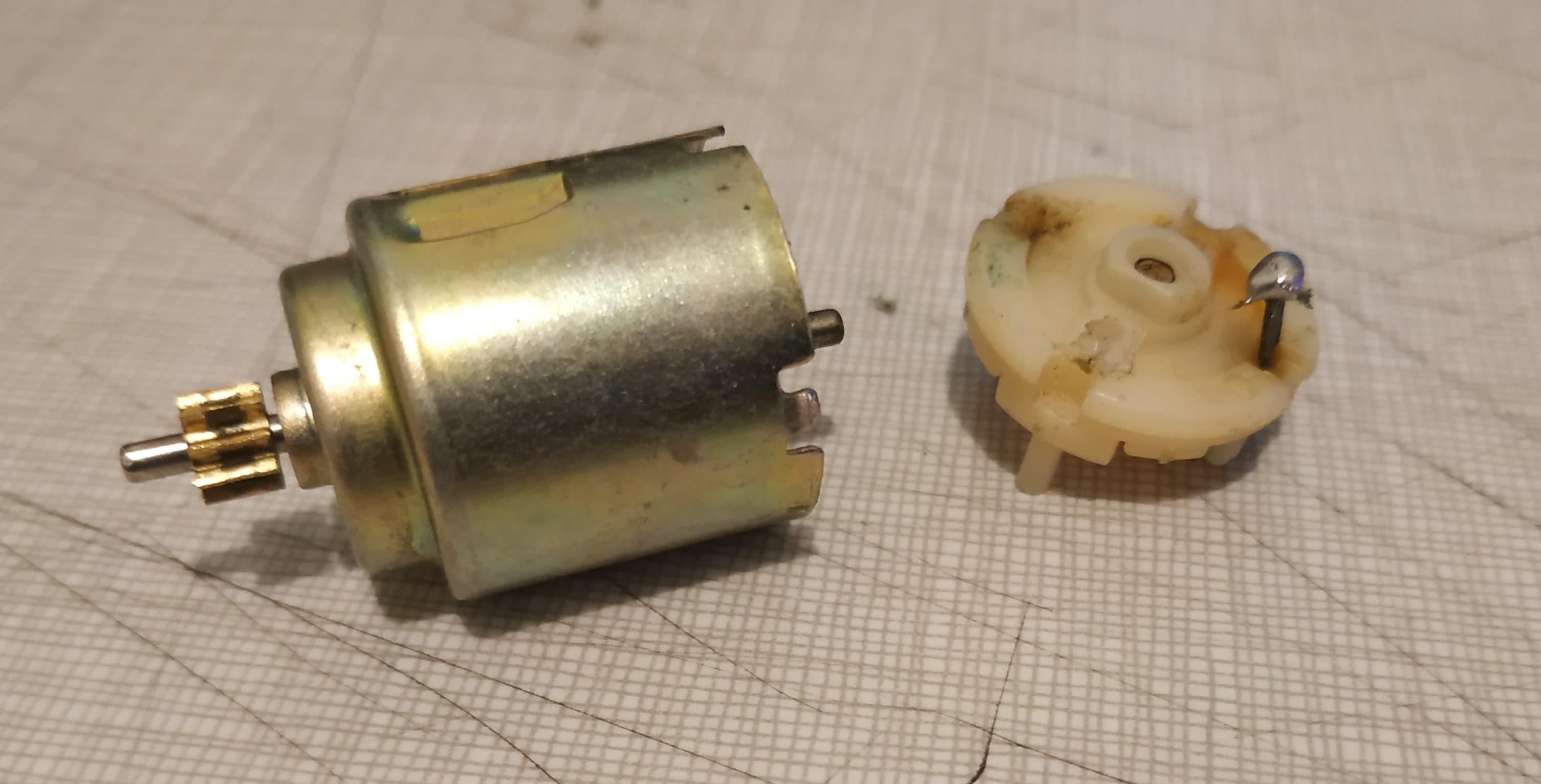
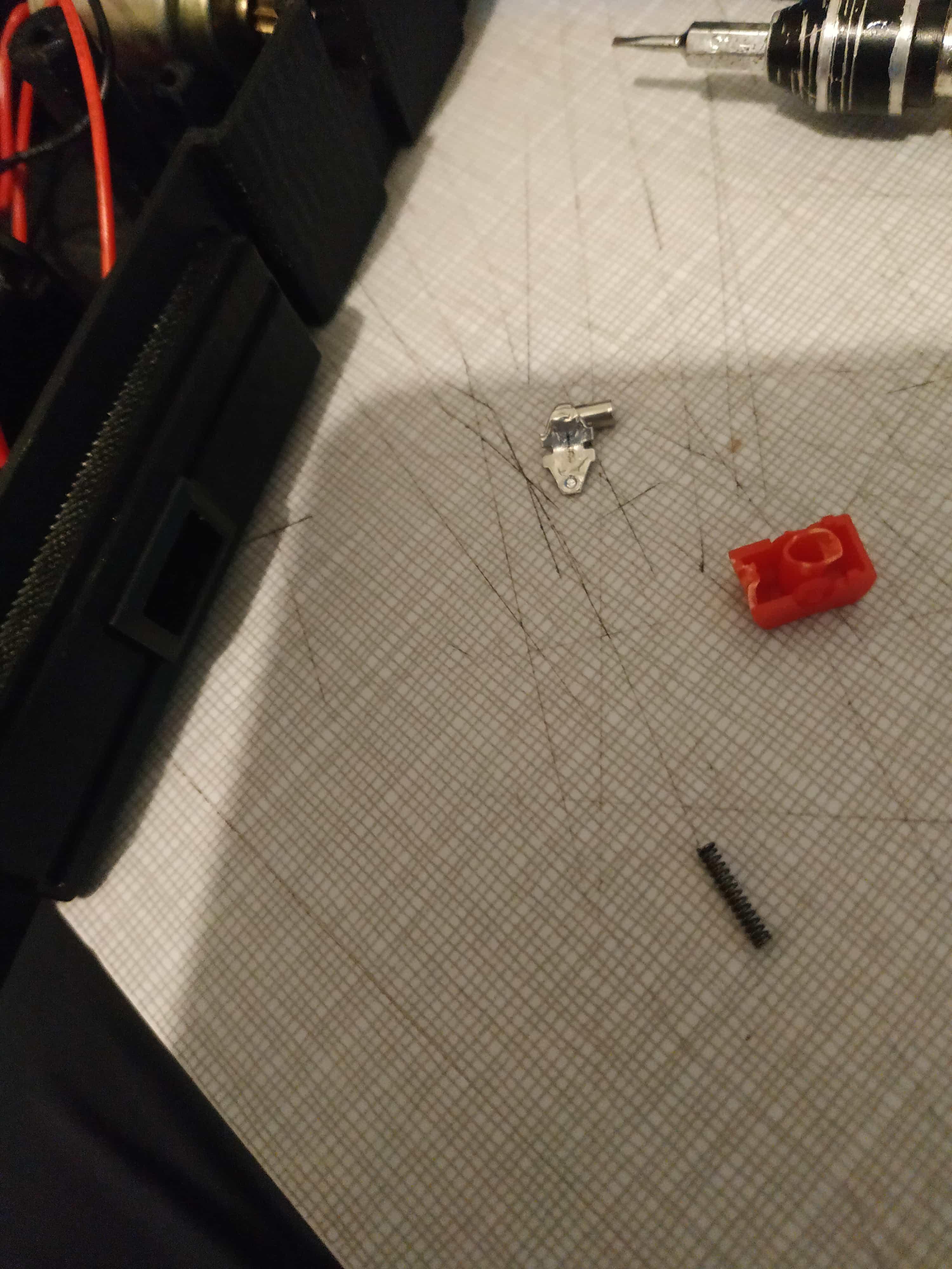
RIP old motor
Well that’s just great, isn’t it? So close to putting this whole thing together, and the motor goes and does a thing like that.
To be fair to the motor, it is probably more than twice my age at this point. And the power terminals were small and rusted. When I tried to wire the motor up, then put it in place, the tiny bit of tension that was on the wire at the time ripped one of the terminals clean off of the motor.
I tried to take the motor apart to put the terminal back. Would you believe it, it actually worked! I somehow managed to perform a very delicate repair on a very old motor. Thing is, ugh… the same issue may have happened again.
The main problem was, the motor was round, so I didn’t know how I was going to properly mount it. I really shouldn’t have, but I tried hot glue. That honestly might have worked. But because of the tight space the motor had to fit into, I ended up making a mess with the glue, and ended up gluing the motor’s shaft from being able to spin.
As I scrambled to try to remove the glue before it went hard (I don’t know why I didn’t just wait and try to remove it when it wasn’t hot) the “repaired” power terminal fell off again, taking the wire with it.
I took the motor apart one last time, and attempted another surgery on it, with all the precision of a crazed butcher. Needless to say, it didn’t take very kindly to it. My theory is that the motor’s “brushes” (little strands of metal that connect the power terminals to the rotating shaft of the motor) just couldn’t withstand the motor being taken apart again. I tried to make it spin again, desperately zapping it with electricity (from the 3.3V rail of my Arduino microcontroller board) like I was using a defibrillator on it. No dice, sadly.
But I decided then and there that the dream wasn’t dead yet. One way or another, I was going to get this thing to move.
I scavenged around and found a little “130 type” DC motor in my box of motors. Close enough in size, although I didn’t know anything else about it. I tried to get the gear off the end of the old motor, but it didn’t seem like it was going to budge. Which makes sense - if it could easily be removed, how could it have held on all those years?
But now I needed a gear. All I knew was that it had nine teeth and a ~2mm hole in the middle. Wouldn’t you know it, that’s all the information I needed!
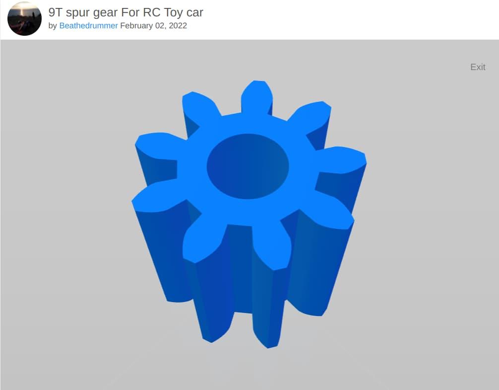
The internet is truly a magical place sometimes. Where there's a model, there's a way!
Thanks to @beathedrummer on Thingiverse, I found this gear design.
Granted, it was going to be a very small print. I honestly wondered if my Prusa would be up to it. But it worked, now I had a motor and a gear!
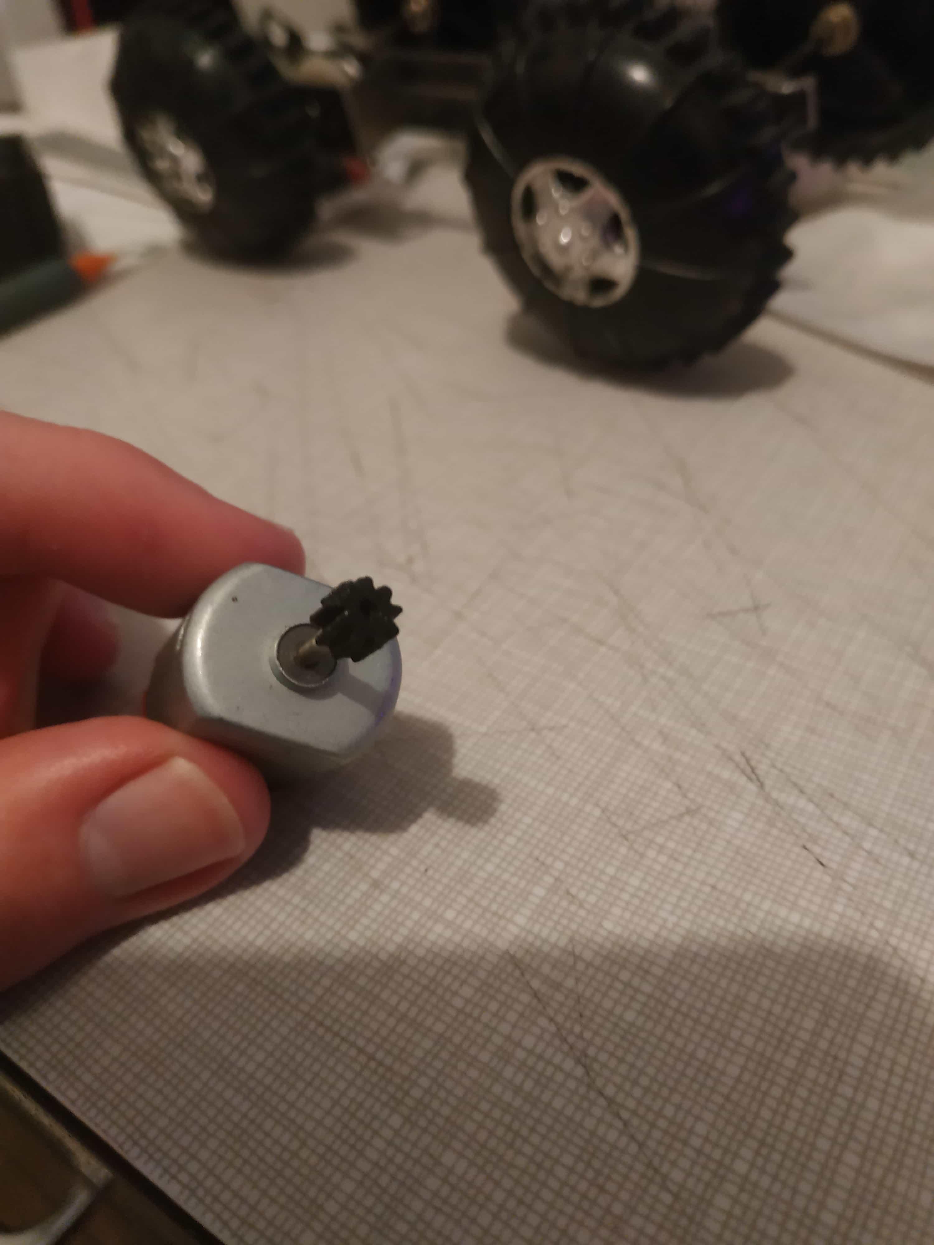
Will this work? I got nothing to lose!
Now, I understood the issue with using a plastic gear. Namely, it wasn’t going to last nearly as long as a metal one. The friction of spinning so fast against the metal gear in the buggy’s gearbox was surely going to wear the poor plastic gear’s teeth out in record time. But it was worth a try, so I tried it. I wasn’t about to go buy a metal gear before doing all the testing I could with the materials I had on hand.
(Did someone say Metal Gear? - sorry I had to)
And wouldn’t you know it, the crazy plastic gear worked! I don’t have any footage of it in action, because the motor I was using required 5V, which could not be supplied by the two AA batteries I was using (which could output, at a maximum, 3V when connected in series). And I didn’t run it for too long, because this motor was really fast. Like, way too fast, and I was worried that it would break the buggy’s gearbox if I let it run for a while. It did not sound pleasant, let me tell you. But it worked, at least well enough for me to move on to what I hoped would be the final stretch.
Along the way, I was able to dig up the datasheet for the original motor. Or at least what I believe is the modern-day equivalent of it. It was a bit of a scavenger hunt, but I cross-referenced markings on the motor and eBay listings, and found its model number - a Mabuchi RE-260RA. As an aside, Mabuchi is one of those companies that has their products just about everywhere, but almost nobody ever talks about them. They make a lot of little motors, and clearly have been doing so for quite a while. Since the buggy’s old motor bore a tiny Mabuchi logo.
In retrospect, I think it was probably the 1.5V version. Since like I said, there used to be two little lightbulbs connected to the buggy too. And with 2 “C” batteries that could provide 3V in series, the voltage drop across the two lightbulbs (which were little incandescents, not LEDs, so I’d imagine the drop would have been quite high) would leave maybe 1.5-2V left for the motor.
But I thought “I’m using 2 AA batteries and no lightbulbs, so I should go for a 3V motor”. Not an unreasonable idea, but I would eventually realize the situation was a bit more complicated.
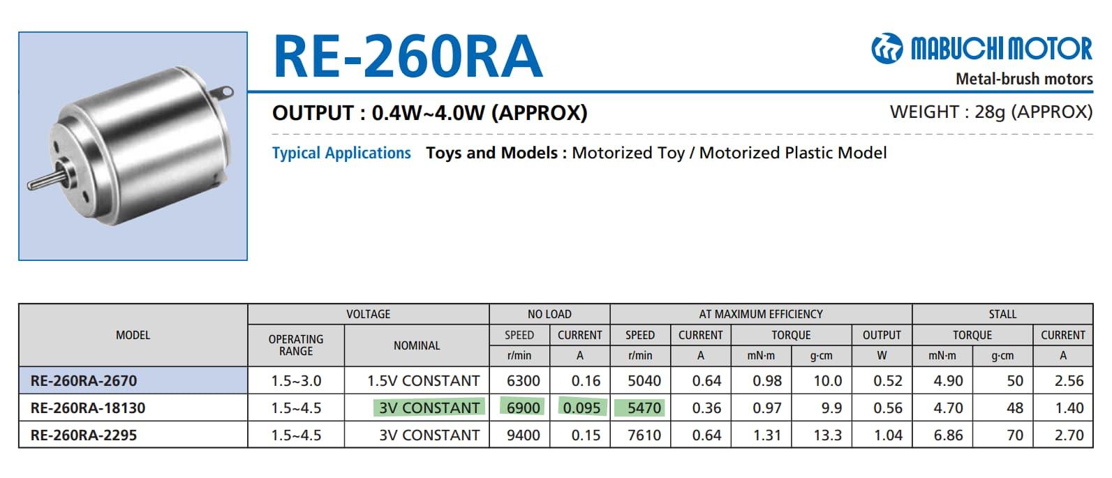
I took the highlighted numbers to help me in my quest to find a new motor
Now, I didn’t want to get this exact motor again for a few reasons. First, I don’t think they’re that easy to find, and they would not have been cheaper than the option I eventually went with. Second, I really didn’t want another round motor, because I couldn’t figure out how to properly mount it. The common “130” form factor, with a flat bottom and terminals on the top instead of the end, was more appealing to me.
But these values for voltage, RPM, and current were what I took with me on my search. At first, I looked for a motor that matched my requirements and had a nine-tooth gear on the end of its shaft. But I eventually abandoned this idea, since I was able to find some brass gears on Amazon that fit my requirements. I might not have been able to remove the old gear from the old motor, but surely I could add a new gear onto a new motor, right? Right?
For once, yes, actually. It was totally doable, and in fact easier than expected. The hard part was having to wait several weeks for the gears and eventually the motors I picked to arrive from Aliexpress. I picked 3V motors (yes, I bought more than one of them, having become paranoid thanks to the switch incident) that had very similar characteristics (RPM, starting current, and torque) to the old motor.
While waiting for the new gears (yes multiple gears, because paranoia and the smallest I could find was a 10-pack) and motors to arrive, I set to work on the last stage of the 3D design.
Now that I was using a 130 motor, of known dimensions with a flat bottom, I could design a much more secure mount for it. It took a few iterations, but I eventually settled upon a design that gave me a bit more wiggle room when putting everything together, but came with a clip I could screw in place on top of the motor.
As an aside, I can’t recommend the site GrabCAD enough for projects like these. There are many high-quality 3D models available for free download from GrabCAD, that you can use as references in your projects. I was able to find a reference model of a 130 motor that helped me design a very accurate method of mounting my motor to the base of the buggy.
Progress, people. Progress! Note how I used some foam tape to move the motor up a bit, and to mark some lines on it to help with the next design iteration. But eventually, I was able to ditch the tape entirely, and the motor fit just fine on its own
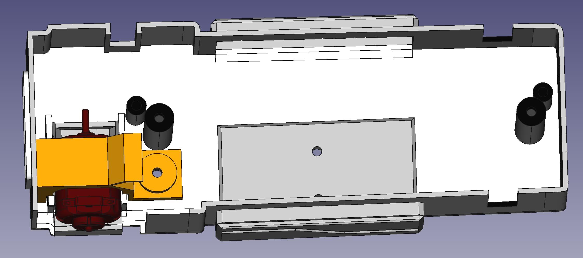
Here's a FreeCAD screenshot of my final design. Note how the base has a 'seat' for the motor, and the clip can come from above and be screwed in place on top of it
Now, a screenshot is all fine and good. But I think I can do one better for you. Thanks to the power of our new blogging engine, behold the buggy’s new base in all its 3D glory:
Pretty cool, huh? You can rotate the model with your mouse, or just sit back and watch it slowly autorotate for you!
You’ll notice a few things I tried to do to spruce up the model and make it a little less “boxy”. First of all, I added some accents (like the lines on the sides, the cut-out on the front, and the “license plate” on the back. The battery holder has a raised bit to sit on, so the screws that attach it to the base don’t poke through the other side. And there’s symmetry in the protrusions I made on the sides, to accomodate the switch on one side and the battery holder on the other. Because they needed a little bit more space to fit in nicely. I also made a cut-out next to the motor, because that part of the base was just getting in the way of properly positioning the motor. The cut-out is covered by the right-rear wheel anyway, so I thought it was a reasonable compromise.
And if you look at the underside of the buggy’s base, you’ll see the various holes I made in it for screws. Two screws for the drivetrain, which face down. Two screws that go up into the top part (which require bigger holes to fit the screw heads in). Two screws for the battery holder. And finally, a screw from the bottom to hold the motor clip in place.
Speaking of the motor clip, here’s its 3D model:
The motor clip fits over the contour of the top of the motor, and locks snugly into the corner of the buggy’s base. It’s held in place with a small M3 screw that comes from the underside of the buggy’s base. And there’s a little flap on top to route the motor’s wires on top of. In the real thing, I put a piece of electrical tape over this flap to keep the motor’s wires in place. This bit of the design was necessary, since the axle is literally right there and I didn’t want any wires getting caught in any moving parts.
Yes, you read that right. Once the motors and gears finally arrived, I was able to make a couple of adjustments to the base of the buggy, to account for the slightly shorter shaft of the new motor versus the 5V one I was testing with (you remember, the one that had the plastic gear on it). I noticed that my brass gears had a slightly smaller hole on one side, so I put one of them onto a piece of wood, with the slightly larger hole facing up. With another piece of wood between the motor and the hammer, I gave the motor a couple of good bops, and it found its way into the gear.
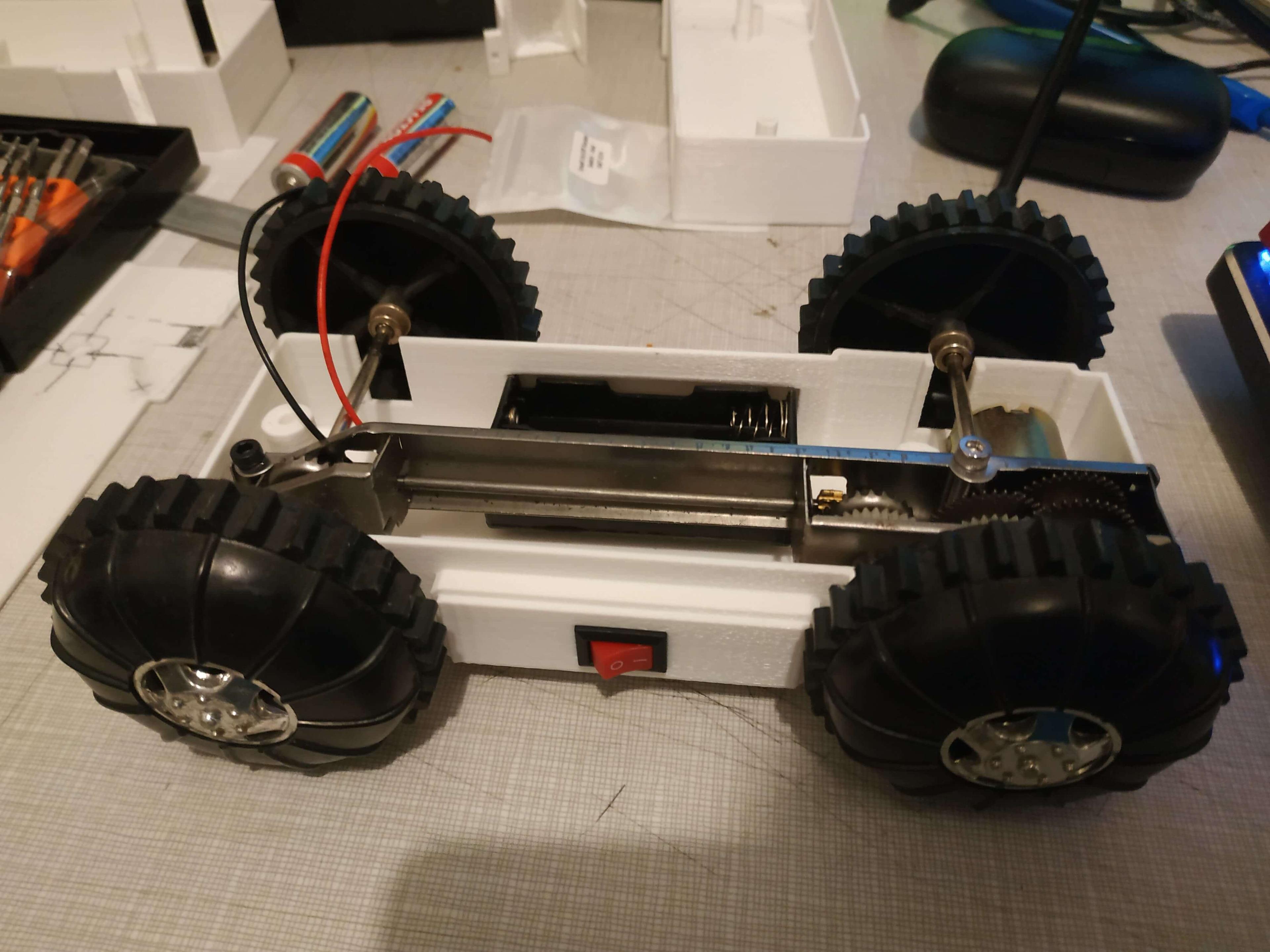
It was a tense moment of anticipation, as I fit the now-geared motor, first into the round hole in the drivetrain’s gearbox, then into the slot I made for it in the buggy’s base. Propping up the base on an old prototype base so the wheels were in the air, I zapped the motor’s terminals with 3.3V (eh, close enough to 3V) from my Arduino. With a whirr, it sprang to life. My metal, sorry brass gear meshed perfectly with its counterpart in the buggy’s gearbox. And literally just like clockwork, the wheels were a-spinning!
With that, I was ready to go. It was still a rather nerve-racking experience. Because as I’ve said, I’m not the best at soldering, especially not tiny components in small spaces. But I figured my best shot was to take it slowly and methodically. After confirming that my new 3D printed base was going to do the trick, I attached the battery box to it. I then popped in the switch, and carefully soldered one terminal to the red wire of the battery box, and another to a separate jumper wire.
After a couple of false starts and averted mini-disasters (though nothing would phase me too much at this point, as I now had spare parts for my spare parts), I got the motor connected. I was able to solder the ground wire from the battery box, and the other side of the jumper wire connected to the switch, to the motor. Basically the simplest circuit you could ask for, and it still took everything I had in me to make it work. But hey, I’m self-taught and this is the only way I can learn.
And now came the moment of truth. I slid two “AA” batteries into the holder, and flipped the switch.
…
Ahem, I said, I slid two “AA” batteries into the holder, and flipped the switch.
…
Seriously? Nothing? All this work, and nothing? This couldn’t be. Surely it was my soldering. I took out my multimeter, in continuity mode. Nope, everything that should have electrical continuity does. I gave the motor 3.3V again from my Arduino, after taking the batteries out and connecting the Arduino’s wires to the battery holder’s terminals. And wouldn’t you know it, away it spun!
Now, I don’t claim to be a physicist, or engineer, or anything more than a business major who over-relies on my own intuition. So I’m not going to try to explain exactly why nothing was happening when I flipped the switch. All I’m going to say is that, to my incalculable relief, it worked when I put brand-new batteries into it!
My running theory is that brand-new AA alkaline batteries just barely have enough voltage and current to get the motor spinning. It’s possible that rechargeable NiMH batteries (which have a slightly lower voltage but a slightly higher current rating than alkaline AA batteries) might be a bit better, but I haven’t tested them in the buggy, yet. Truthfully, I haven’t touched the thing after putting it back together and testing it out. I don’t really want to jinx it.
But I think I’ve gained a real appreciation for the cleverness of the original designers of this buggy. See, it originally used “C” batteries. Like “AA” batteries, they output 1.5V (nominally, at least). But they can provide quite a bit more current than AA batteries, and I think that’s an important point. Although they take up a lot more space, “C” batteries made sense for the original design of this buggy, because the motor could keep running on them for a long time. Whereas with my (electrically) sloppy redesign, the batteries will probably not be able to power the buggy for half as long, and it is slower and less erratic than I’m sure it used to be. To me, it just goes to show that even a “sub-optimal” idea can work, given enough creativity. So I definitely applaud whoever came up with the design for this thing.
I did some research on these things. Apparently they’re still sold as “constant velocity cars“ from some science vendors (which all seem to have incredibly overpriced shipping, by the way). And back in the day, they were known as “flip-over buggies” that would hit a wall, flip upside down, right themselves, and continue in the opposite direction.
My redesign doesn’t seem to have nearly enough “oomph” to allow it to flip over when hitting a wall. And it seems to want to veer a bit to the left. But hey, it was completely busted, and now it can roll once more, even if a bit slower than before. And now I have enough spare parts for it to probably outlast me, so that’s kinda funny. I think I’m going to keep the original base, in case I ever want to revisit this project in the future and need a good reference (but not the motor, that’s toast).
Some day I might want to add some RGB headlights, better batteries, USB-C recharging, a proper motor controller board, and maybe a 3D printed roll cage and a little figure sitting in the driver’s seat. But for now, the buggy has served its purpose.
I like to treat these types of projects as ways to trick myself into learning new things. OK, self, you want to make this buggy ride again? You’re going to have to get comfortable with FreeCAD, push your new 3D printer to its limits (at least with the plastic gear), learn some interesting things about rocker switches and DC motors, go for some internet scavenger hunts, and face your aversion to soldering in small spaces.
And you know what, if that’s all this project was, I wouldn’t hesitate to call it a resounding success. But it was more than just a learning opportunity, so get ready to enjoy some shots of the finished product, and some video footage of the buggy back on its wheels after all these years.
But remember, sometimes you need to take a good hard look at your project, re-evaluate its scope, and push to complete it, even if completion falls short of your original plan. Because plans change, often for good reasons, and you should learn to be open to that. And a completely-finished project, even one whose original scope was limited, is so often better than a half-finished project that’s left on the cutting room floor.
In closing, thanks so much for reading this far, and following along for the ride, bumpy though it may have been. I sincerely hope you got something out of this post, on a technical and a personal level. I hope I was able to impart just how frustrating, exhilarating, curiousity-inducing, educational, and ultimately satisfying this project was for me. And I hope you can find your own Buggy Project - something that draws you in, takes everything you can throw at it, and forces you to pick up some new skills and confidence along the way.
Until next time, this is Matthew Piercey signing off. Catch you in the next project!
Ah, nothing quite like seeing an idea take shape, piece by piece
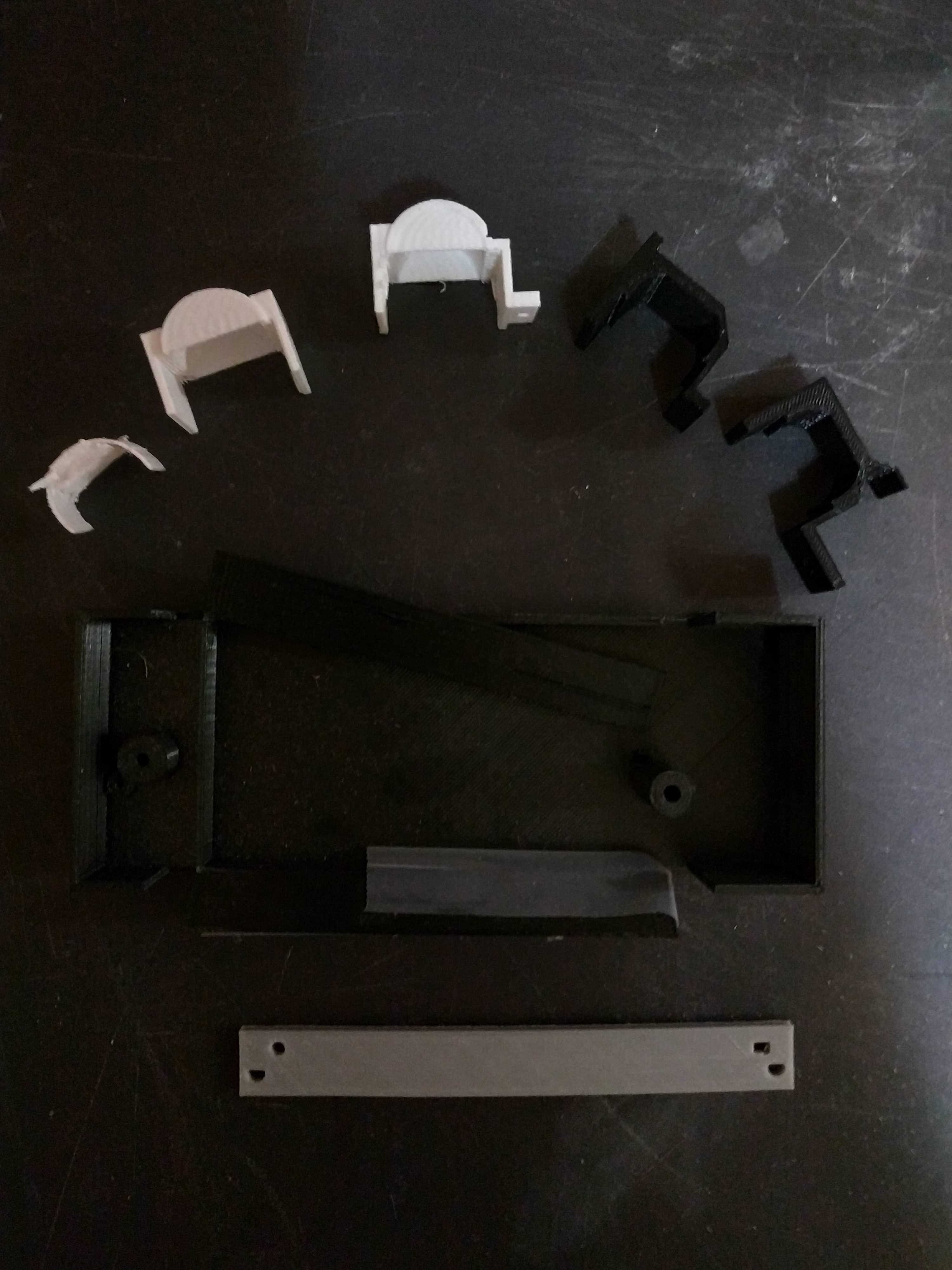
That grey rectangle was where this whole thing began. And those earlier motor clips were actually designed in TinkerCAD, if you'll believe it.
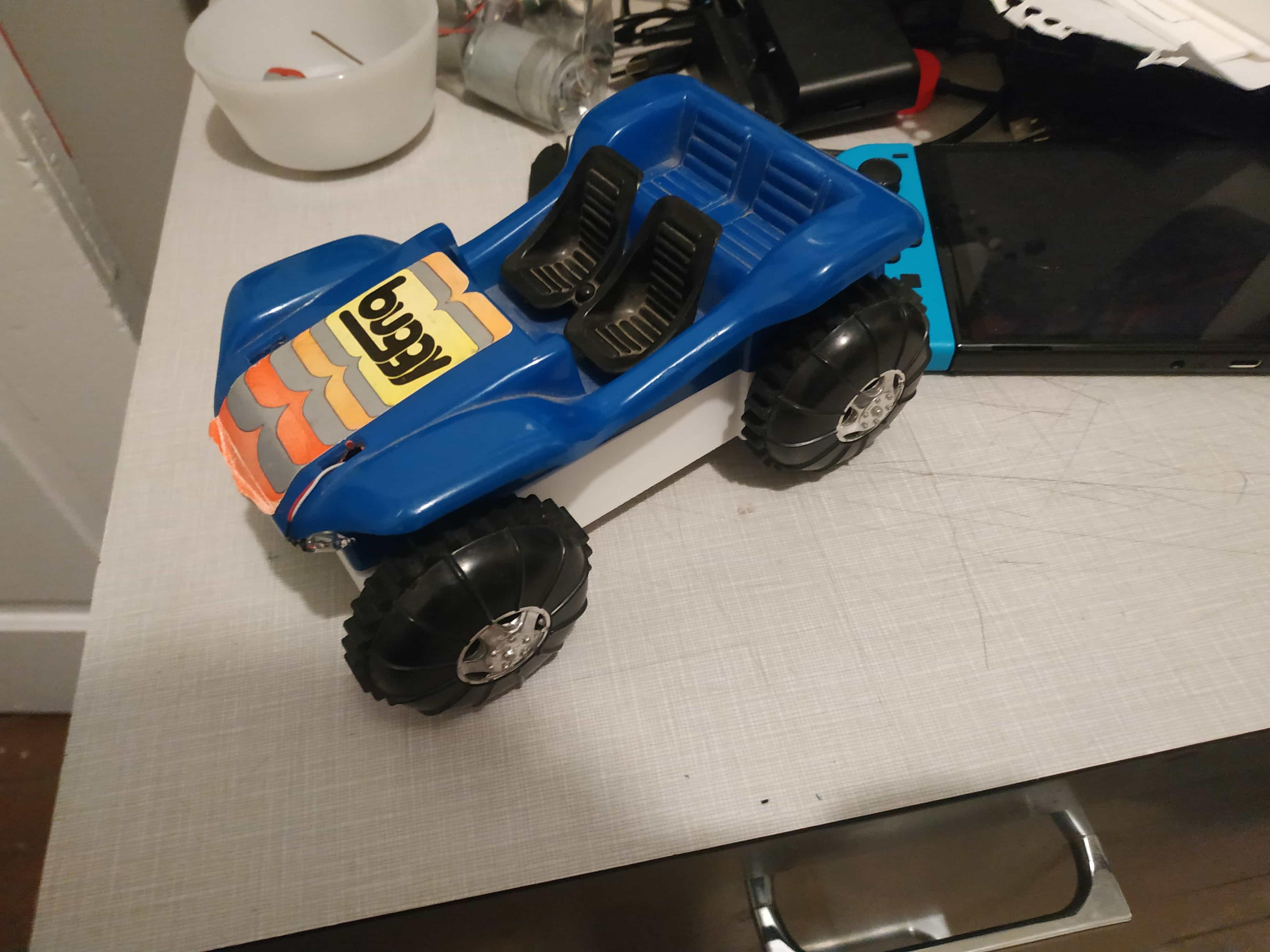
It took a lot to get here, but we finally made it!
From the back
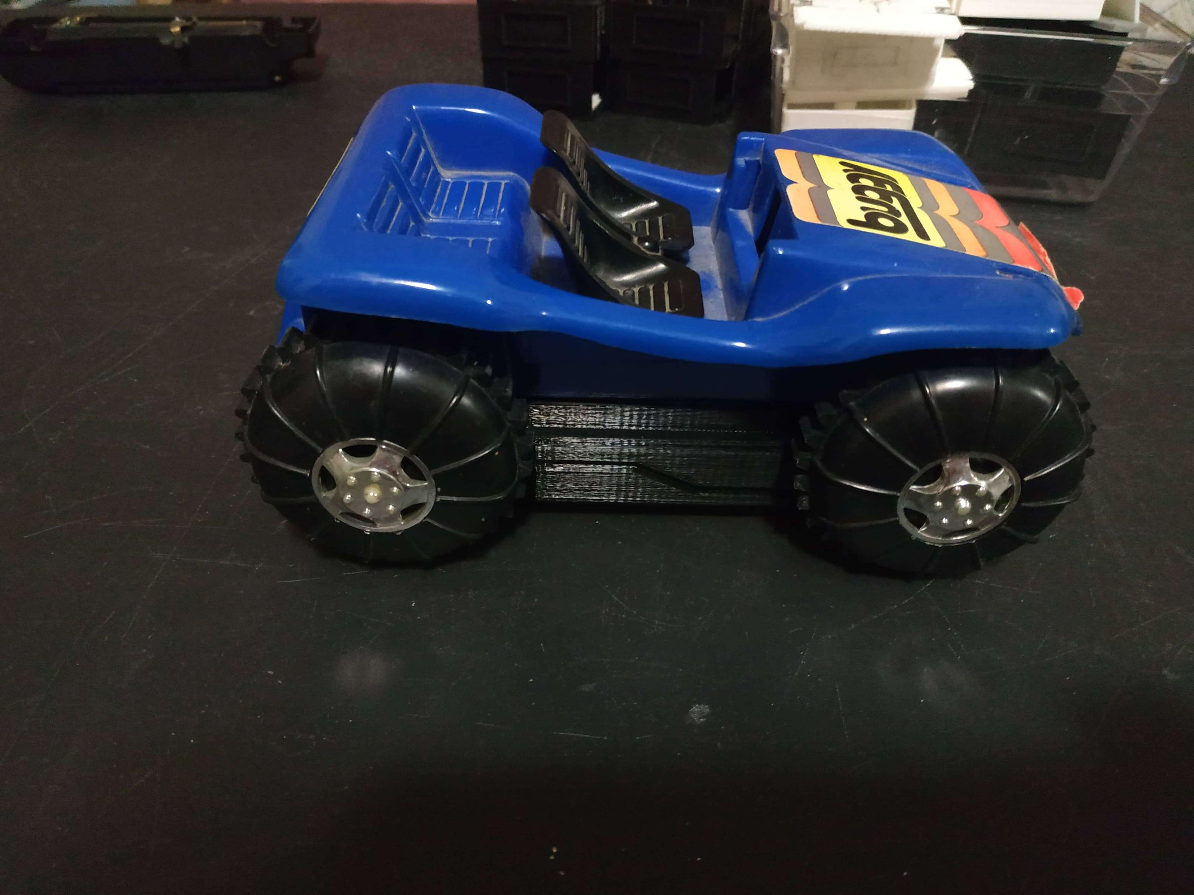
From the side, check out that "lightning bolt" design I tried to make

From the other side. I just love how good the switch looks here
Looking pretty good, if I do say so myself